File:Heatpump.svg
Jump to navigation
Jump to search

Size of this PNG preview of this SVG file: 750 × 438 pixels. Other resolutions: 320 × 187 pixels | 640 × 374 pixels | 1,024 × 598 pixels | 1,280 × 748 pixels.
Original file (SVG file, nominally 750 × 438 pixels, file size: 34 KB)
This file and its description are from Wikimedia Commons.
Summary
| Description |
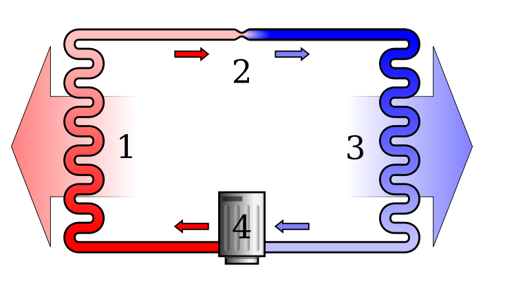
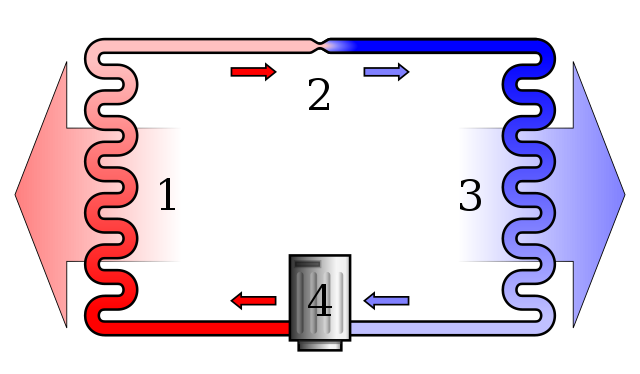
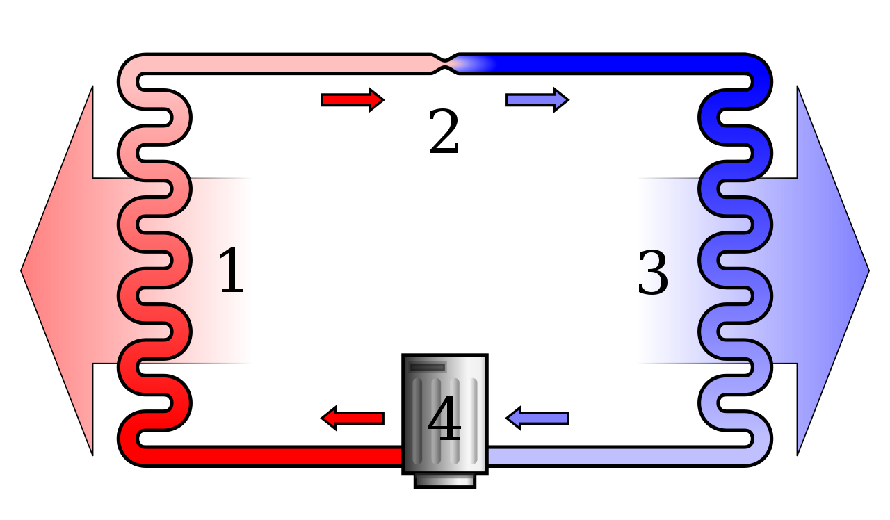
English: Diagram of a phase change heat pump.
Note that the arrows in the diagram are meant to indicate the flow of air and coolant; they do not correspond to heat flow, which in the system depicted is (generally) from right to left. Deutsch: Schema einer Wärmepumpe mit Phasenwechsel. |
| Source | Own work |
| Author | Ilmari Karonen |
| SVG development | This diagram was created with Inkscape…important. This diagram uses embedded text/digits. |
Legend
- Condenser coil (hot side heat exchanger, gas cools and liquifies)
- Metering Device (liquid expands and cools)
- Evaporator coil (cold side heat exchanger, liquid vaporizes and heats up)
- Compressor (gas is compressed and heats up)
- Red = Gas at high pressure and very high temperature
- Pink = Liquid at high pressure and high temperature
- Blue = Liquid at low pressure and very low temperature
- Light Blue = Gas at low pressure and low temperature
Licensing
| I, the copyright holder of this work, release this work into the public domain. This applies worldwide. In some countries this may not be legally possible; if so: I grant anyone the right to use this work for any purpose, without any conditions, unless such conditions are required by law. |
File history
Click on a date/time to view the file as it appeared at that time.
| Date/Time | Thumbnail | Dimensions | User | Comment | |
|---|---|---|---|---|---|
| current | 09:22, 5 April 2017 | | 750 × 438 (34 KB) | wikimediacommons>Jahobr | cleanup, I hope errors are fixed |
File usage
The following page uses this file: