Key:design
Jump to navigation
Jump to search
| Description |
|---|
| Describes the design of poles or pylons carrying high voltage electricity cables |
| Group: power |
| Used on these elements |
| Requires |
| Status: de facto |
| Tools for this tag |
|
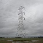
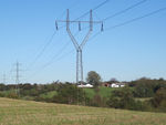
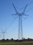
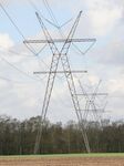
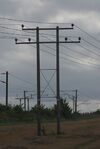
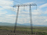
This key describes the design of poles or pylons carrying high voltage electricity cables. The main parameters are the number and positions of cross-arms. Cross-arms which only serve as support for earth wires should not be considered. See examples with suggested values below.
Towers or pylons
| Picture | Key | Value | Röntgen icon | Description |
|---|---|---|---|---|
| design=* | one-level | A tower having cross-arms at a single level only. | ||
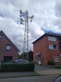
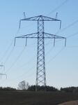
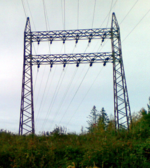
| design=* | two-level | A tower having cross-arms at two levels. | ||
| design=* | donau | A common sub-type of the two-level tower. It is characterized by having one conductor on each side at the upper level and two conductors at each side on the lower level. The "Donaumast" is widely used in central Europe. | ||
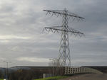
| design=* | three-level | A tower having cross-arms at three levels. | ||
| design=* | barrel | A common variation of the three-level tower. It is characterized by the middle level cross-arms being longer than the upper and lower cross-arms giving the conductor arrangement a barrel-like shape. | ||
| design=* | asymmetric | A two- or three-level tower carrying only one circuit and having the conductors arranged in an asymmetrical layout. | ||
| design=* | triangle | It has cross-arms at three levels providing a triangular arrangement of the conductors. | ||
| design=* | flag | All conductors are located at one side which forms the tower either a flag (hence the name) or letter "E" shape depending on the type of insulator and line attachment used. | ||
| design=* | donau;one-level | A three-level combination tower effectively being a Donau tower having an additional lower level, often used for circuits of a lower voltage than those at the upper levels. This tag better describes the design than just using "three-level". | ||
| design=* | barrel;one-level | Similarly to the previous entry, a combination tower, this time consisting of a barrel design on top and a one-level at the bottom. For any other towers that similarly are a combination of two other designs, the value for design=* is a similar semicolon-separated combination of the top and bottom designs. | ||
| design=* | four-level, six-level, nine-level, ... |
A tower having cross-arms at four or more levels. These tall towers may carry four or more circuits. | ||
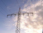
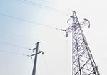
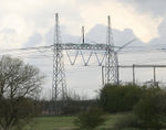
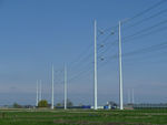
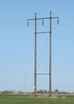
| design=* | delta | A y-shaped tower having a horizontal cross-beam between the two top structures. All conductors are attached to the cross-beam. It is mostly used for a single circuit. A variation or subcategory is the French "chat", "cat" in English, towers shown in the second image designed for dual circuits. | ||
| design=* | guyed_delta | A guyed variation of the delta tower | ||
| design=* | delta_two-level, delta_three-level |
Delta tower having two or three cross-beams. Suitable for three circuits. | ||
| design=* | y-frame | Similar to delta tower but there is no horizontal cross-beam between the two top structures. The middle conductor is supported directly by the top structures. | ||
| design=* | x-frame | A variation of the y-frame tower having two legs. It is suitable for carrying a second lower voltage circuit on a crossbeam below the joint. | ||
| design=* | h-frame | A tower type having two (or more) separate pylons or poles connected by a beam to which the conductors are attached. The cross-beam extends beyond the vertical structures such that not all conductors are located between the vertical structures. The h-frame tower is mostly used for a single circuit, but can be found as dual circuit as seen in the second image. | ||
| design=* | h-frame_two-level, h-frame_three-level |
Designs like the h-frame tower, but having cross-beams at two or three levels. | ||
| design=* | guyed_h-frame | A guyed version of the h-frame tower supported by guy wires, common in e.g. Scandinavia. Compared to the self-supporting h-frame tower this design normally has non-vertical legs. This detail is useful for distinguishing self-supporting towers from guyed towers in aerial imagery etc, since the guy wires are usually too thin to be directly visible in such imagery. | ||
| design=* | portal | A tower type having two (or more) vertical structures connected by a horizontal cross-beam. All conductors are supported between the vertical structures (unlike the h-frame tower). This design is mostly used as termination tower at substations. | ||
| design=* | guyed_portal | Guyed version of the portal tower | ||
| design=* | portal_two-level, portal_three-level |
Two and three level versions of the portal tower. | ||
| design=* | guyed_v-frame | A guyed tower type that is mainly used for ultra-high voltage lines e.g. in North America. | ||
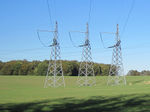
| design=* | monopolar | A tower having no cross-arms, with insulators mounted on the tower itself. Mostly used as an anchor tower at very high voltage and/or long spans. This tower type is typically used in groups of three, with each carrying one phase. There are two recommended options for mapping such a group. Either map all three towers and connect the power line to the middle tower. Or map only one tower and add the attribute triple_tower=yes to the tower. | ||
| design=* | guyed_monopolar | A guyed version of the monopolar towers. | ||
| design:name=* | When the tower design has been given a specific name by its designer it can be indicated by this tag, such as Wintrack (The Netherlands), Eagle (Denmark). | |||
Poles
| Picture | Key | Value | Röntgen icon | Description |
|---|---|---|---|---|
| design=* | one-level | A pole with a single cross-arm, usually supporting only one circuit. This is the default type. | ||
| semi-horizontal_one-level | A pole with one cross-arm, but with one conductor placed offset (i.e. on the top of the pole). | |||
| two-level | A pole with two cross-arms, usually supporting two circuits. Poles with two cross-arms, with two conductors supported on the upper cross-arm, and four conductors mounted on the lower cross-arm (resembling design=donau on power=tower) are considered two-level poles. | |||
| three-level | A pole with three cross-arms, usually supporting one to three circuits. | |||
| four-level | A pole with four cross-arms, supporting four circuits. | |||
| asymmetric | A pole with two cross-arms, but supporting only one circuit in a right triangle configuration. One conductor is mounted on the upper cross-arm, and the two conductors are mounted on the lower cross-arm, or vice versa. | |||
| armless_asymmetric | Variant of the asymmetric pole, but with insulators mounted on the pole instead on the cross-arm. | |||
| flag | Variant of the asymmetric pole, but with either three (single-circuit) or six (double-circuit) cross-arms. All insulators are mounted and facing at one side or direction which make the pole a flag-like appearance due to their formation (hence the name) or letter "E" shape depending on the type of insulator and line attachment used. If V-shaped insulators are used on a pole, the pole resembles the flag of Nepal but with only an extra V-shaped insulator that forms into a triangle shape when this type of insulator is mounted on a pole for single-circuit poles and on some poles, a support for overhead ground wire is used. For double-circuit poles, the insulators are equivalent to three flags of Nepal (six V-shaped insulators). Anchor poles can have horizontal insulators with an insulator in between, forming an anchor shape hence the name of a line attachment. | |||
| triangle | Variant of the asymmetric pole, but with three cross-arms. Two insulators are mounted on the uppermost and lowermost cross-arms, and one insulator is mounted on the middle cross-arm, forming their formation a triangular formation. This is usually used on suspension poles, but can also be used on anchor poles, along with pole-mounted insulators. | |||
| bipole | A pair of closely spaced but non-touching poles. The conductors are typically mounted between the poles. There are no cross-arms. Known as 'Wintrack' in the Netherlands. Both poles can either come in a flag or triangle pole design. The bipole should be mapped as a single pole. | |||
| armless_triangle | Variant of the triangle pole, but with insulators mounted on the pole instead on the cross-arm. Two insulators are placed on one side of the pole, and one insulator is placed on the other side, in the middle position of the two insulators on the other side. | |||
| flag | A pole without cross-arms, with insulators mounted on a vertical arrangement. The design is similar to the flag design for power towers (see Tag:power=tower#Tower design. They usually use pin insulators, but may use strain insulators when used as an angle pole on a sharp angle or line termination point (either, line_attachment=anchor,line_management=termination, or line_attachment=suspension) or both strain and pin insulators when used as an anchor or termination pole on a straight line power line segment. | |||
| semi-vertical | A variant of the flag design, with one insulator longer than the two others. These are always used as suspension poles. | |||
| delta | A pole with two insulators on two sides of the pole, and one insulator on the top of the pole. Unlike in delta tower, "delta" means a conductor configuration than a pole design. | |||
| h-frame | A pole type having two (or more) separate poles connected by a beam to which the conductors are attached. The cross-beam extends beyond the vertical structures such that not all conductors are located between the vertical structures. | |||
| h-frame_two-level, h-frame_three-level |
Designs like the h-frame pole, but having cross-beams at two or three levels. | |||
| monopolar | A pole without cross-arms, with one insulator, either placed on the side or on the top, or an insulator set mounted of the pole. This typically hold single-wire lines, like single wire earth return systems on less populated rural areas or single-wire systems serving light loads, like houses or small businesses, or secondary distribution lines, including three-phase systems or split-phase systems. | |||
| guyed=* | yes | A pole with guy wires, used to stabilize it on a turning or terminating segment of a power line or to balance it on unbalanced power lines. | ||
| pole | A pole with another pole, placed diagonally on the side and serving as a guy wire support. | |||
| design:incomplete=* | yes | A pole that supports only a number of conductors than the design is capable of. |
See also
- 2012 de facto proposal Talk:Tag:power=tower#Properties of transmission towers for design=* on power=tower
- 2017 proposal Proposed features/Power pole extension which adds further values to the design=* scheme, additional values are especially used for power=pole
