Node Networks
This page about Node Networks describes the current practice in the Netherlands. Other communities may, and probably will, have different practices. Node Network mapping is still in development. History and reasoning behind choices are described to help people make up their minds about these matters.
If you just want to know how it's done, Jump to the tagging instructions!
Note that we will use Node with a capital N to refer to the Node network Nodes, as opposed to nodes in general OSM mapping.
What is a Node network?
Basics

Prototype: A Node network consists of marked junctions called Nodes, and Routes interconnecting the Nodes. On the road, every Node is marked with a number, code or name, and it has pointers to adjacent Nodes in different directions. Put differently, two adjacent Nodes always point to each other, which defines the route between these two Nodes. In between the Nodes, the route is waymarked in both directions with arrows or a symbol, often without the Node labels. The symbol is the same for all the routes in a Node network.
The Node network concept can be confusing if you think of routes as e.g. waymarked hiking trails each with its own symbol. You'll have to rethink to make sense of the network routing structure, where you piece Node2Node sections together to make your own unique trip over the network, using the network Nodes as labeled waypoints. Once the Node network is in place, operators can create and offer recreational routes by simply publishingh a list of Nodes representing each route.
For example, in Germany many foot networks use the Yellow Diamond ("Gelbe Raute") as the symbol for a walking network. All routes are waymarked with the same symbol, which doesn't make sense until you understand the node network structure: the symbol leads you to the next Node, and there you choose the next section. Other countries use similar systems.
Note that many variants and styles are used 'in the field'.
Node networks are mainly used for recreational purposes. One finds an area of interest, plans a trip within the network or interconnected networks, and writes or prints a list of Nodes to follow. Of course, this process is increasingly digitized with planner sites, planner apps, gpx output, rendering apps and navigation apps.

Cycle node 272, showing directions to other cycling Nodes

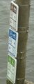
Signpost towards cycling Node 73

Walking Node 74
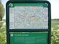
Public map showing a Node network
Canoe, motorboat and open motorboat network Node

.JPG)


Variants
Many Node networks use numbers as labels. Variants include using letters, codes or names instead of numbers, or different colour markings on the Node2Node routes. Arrows and pointers may be replaced with strategically placed signposts, so the user has to look around to find the path leading to the next node on the list. This makes no difference when planning a trip over the Node network. Planned trips in the end consist of a chain of numbers, codes or names to follow. Sometimes additional details such as a colour code are needed.
A particular variant uses coloured routes to interconnect the network Nodes. Often, the coloured routes existed first, and later, where the colour routes started, crossed or touched, labeled Nodes were created. On the road, you cannot choose the next number, you choose which colour to follow. The trip planner app has to add this colour information to the user output. (2021-07-06 One of the two Dutch operators who do it this way has confirmed that they will add the codes to the symbol shields on the Node posts later this year. 2021-11-11 Update: The numbering operation has actually started. 2023-10 Update: the Wandelnet Planner now supports coloured routes, by showing the Node2Node route colours in the user output).
A less useful variant is a Node network by design, but on the road the destination nodes are not indicated at the network Nodes. To make a choice, the user needs external information, e.g. a map showing paths and nodes, or a gpx, or a Node strip indicating the direction. Typically, after some time the operator is made aware of the user problem, and adds a solution to indicate the different directions at the nodes. E.g. the operator adds transparent stickers with the destination numbers.
In Germany, France, Switzerland and Austria, many walking Node networks exist using Node names as labels, instead of Node numbers or codes. Because most networks use numbers or codes consisting of a letter and a number as Node labels, these networks were only recently (2020) recognized as functional Node networks. The tagging scheme, maintenance tools and planners have been adapted (2021Q3) to accommodate named Nodes.
Transport modes
Different transport modes are supported. New transport modes can be added as they appear on the road. The transport modes are indicated by tags in the route relations, in the network relations and on the network Nodes. A letter is used to indicate the transport mode: w Walking, c Cycling, h Horse, i Inline skating, m Motorboat, p Paddling (e.g. canoe). This is the same as for regular (non-node_network) routes.
A specific transport mode may require special or additional tagging. For example, bicycle node networks require intricate handling of route differences according to the direction of travel. The existing route tagging system, using forward and backward roles to record both directions of travel in one route relation, is therefore accommodated in the Node network system, independent of transport mode.
For canoes and motorboats, waterway depth vs vessel depth is important, and lowest obstacle vs heigt of the vessel is even more important. This area still needs some work. Probably extra detail tags will be proposed to hold that information. This is comparable to the colour tag providing extra detail about the route. In software this can be generically handled: if the extra tag is there, it is always handled in the same way, no matter what the transport mode is.
The tagging in principle supports multimode trip planning, but currently (2021-11) no applications offer this capability to the users.
Geographical scope
The Node network tagging system supports the same geographical scopes as regular recreational routes: l for local, r for regional, n for national and i for international. Currently, two scopes, l and r, are in use for Node networks. The Dutch and the Belgians use r for all node networks, because the extent of the networks tended to be regional. The Germans and the French however, tend to use regional scope for cycling networks, but local scope for walking networks, because for cycling the Nodes and routes tend to be regional, while for walking the Nodes and the Node2Node routes are generally local. National and international Node network routes are not currently known, but if they arise, they can be accommodated within the same framework. Other scopes, e.g. intercontinental or (why not) interplanetary, would require a new scope indicator, say g for global, s for solar system, and tools and applications would need to adapt to handle these scopes.
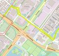
Interconnecting networks with different scopes is still a challenge, which will be addressed in the near future. 2021Q3: One example has popped up in Ghent (B). A local cycling Node network has been created within an area where a regional cycling network already has Nodes. It looks like this development will also happen in other places and also for walking.
Implementation styles
Waymarking on the road or waterways may differ between regions, and may require some getting used to when following the routes on the road or water. Many cycle networks use separate posts and shields for the Node2Node route waymarking, where walking networks often use simple stickers and small shields on landposts, street furniture and trees, or combined with regular route symbols on multipurpose shield posts. Some give the next Node label on every shield, some just use an arrow or shield without a label. In Germany and France, many operators have integrated all waymarking and direction-pointing systems for a particular transport mode into one system of named signposts and shields for all purposes. In Nederland, boat networks and canoe networks use each others Nodes (same numbers), but distinguish the vessel types by a colour code.
The pictures above show a style using metal shields, where the colour, size and an icon indicate cycling or hiking, and the shields show the direction and the Node number you will reach next. The boat Node example shows the use of colours to differentiate between the types of boat.
Different topological styles may be found as well. Some operators use end Nodes (1 route) or middle Nodes (2 routes) at POI's, some don't. Some operators have non-numbered route splittings, where you would expect a netwok Node but there simply isn't one. Some operators use intermediate network Nodes when there are alternative ways to connect two network Nodes; some simply allow two routes between a set of Nodes. Some have loops on a single Node. Some use a single number when choice points are close together; others tend to assign different Node numbers even when the Nodes are only 15 m apart.
The tagging scheme accommodates all those variants, and is versatile enough to allow further variants without changing the basics.
Network maintenance
Node networks are maintained on the road by various (and often changing) operators. Most operators have their own network maps and sometimes a planner site or app. OSM uses the Nodes and Routes as found on the road and in the field. In The Netherlands, mappers are allowed to use the Wandelnet Node route planner https://wandelnet.routemaker.nl/routeplanner/wandelen as a source for the very detailed walking Node network covering almost the whole country.
Sources of data
Survey is of course the most valuable source. Other sources may help. Operators may provide their data as open data (Odbl or comparable). This allows mappers to use that information for OSM. In The Netherlands, mappers are allowed to use the Wandelnet Node route planner https://wandelnet.routemaker.nl/routeplanner/wandelen as a source. Both the Wandelnet data and OSM are (2021) well underway to complete coverage for the Netherlands. Missing parts are still work in progress on the road, but OSM mappers now pick these sections up in a matter of weeks. No matter the source: in the end, maintenance will always rely on survey, because there is no easy way to signal and process individual changes which may or may not be in the OSM database already. Automated synchronization is impossible because of the completely different GIS systems used by source databases.
History
Node networks started out as separate cycling Node networks in Belgium, soon copied by The Netherlands. Later different networks interconnected and the system was also applied to walking. Nowadays, for cycling in Nederland, the whole country is one big Node network; the walking network is almost covering the country, and Node networks for horse riding, motorboat, canoe and inline skating are being rolled out. Other countries are seen to follow this development.
The basics of OSM-tagging of Node networks came from a discussion on talk-nl in September 2008, and it was fleshed out in the months after that. Since then, many things have changed but the basic modeling system is the same. This development is still going on: e.g. the tags for canoe and motorboat Node networks were added in 2018, support for colour routes was added in 2019, and support for named Nodes was added in 2021.
Tagging principles
This page gives the reasoning and the essentials for all Node networks. It explains how we arrived at the current data model. Details for a particular type of Node network can be found on various tagging pages. Variations and rules for particular countries should be described on localized pages.
Tagging is based on the following real-world observations:
- a Node network encompasses a limited geographic area and usually has a name, an operator, a symbol, and optional other specific attributes
- a Node network is a signing and routing system for planning trips and navigating along a chain of Nodes of the planned route.
- the physical elements indicate but are not the same as the network elements. The tagging is designed for routing and trip planning, not for exact location of signposts.
- Node networks tend to grow and connect to surrounding networks, so they tend to merge into larger networks
- Networks have labeled (numbered, coded or named) junction Nodes. The numbers and codes are not unique id's; they are often repeated even within a network. Node names, in contrast, tend to be unique within a network.
- signs at the junction Nodes may or may not show the name of the network or the operator. Network names and operators tend to change a lot.
- there are signs and markings at and between the junction Nodes, indicating how to proceed to nearby junction Nodes. Within a network, one style and one symbol is used for all elements.
- networks connect to other networks in two ways: 1. A Node belongs to two networks; 2. a route connects 2 Nodes which belong to different networks
- routes, in particular cycle routes, can follow different roads depending on the direction of travel. This can occur due to oneway streets, cycle lanes on both sides of streets and roundabouts with split ways
- junction Nodes can be "split Nodes", with multiple identically labeled signs or poles at a short distance from each other (usually less than a few hundred meters)
- sometimes Node2Node routes join/separate some distance from the actual Node. The way(s) between the split/join location and the Node then belong to more than one Node2Node route. This may or may not be within visual distance of the Node for which the split/join point works. This may confuse the user of the Node network.
- some routes do not connect Nodes. They may connect to a city centre without Nodes or to a ferry. They are more like approach routes.
- some of these approach routes join the network in the middle of another route, without an official Node.
- Additional attributes have to be considered for routing, such as access tags on roads, minimum clearance for boats, conditional access, oneway tags for cycleways or implicit cycling lanes.
The objective was and still is, to make the Node networks routable and planner-ready, and renderable as special networks, different than regular cycling, hiking, horse, canoe, motorboot and inline skate routes. So we are building a model for data use, while staying as close to the real world as possible. This can be compared to the way roads are mapped and connected as linear features to enable routing, while in reality they are areas.
The system should be extendable to accommodate new transport or sport types (r*n); node networks of smaller or larger scope (l*n, r*n, n*n, i*n) and different network types (network:type=*).
The system should also be scalable without any hard limit to cope with the possibly very large number of elements involved.
This has been achieved as follows:
- Not the actual physical features (poles, signposts, arrow stickers and roads) are mapped and tagged, but the Node2Node routes and the intersections of the ways of the Node2Node routes.
- Junction nodes are tagged with network:type=node_network and with the Node number or code as STn_ref=* (where T indicates the transport mode: w for walking, c for cycling, h for horse_riding, i for inline_skating, p for paddling e.g. canoe, m for motorboat; S indicates the scope: l local, r regional, n national and i international). Since 2021 named Nodes are supported, tagged as STn_name.
- The intermediate waymarks are not tagged as features, because they just indicate the route i.e. which ways to put in the route relation.
- Each bidirectional Node-to-Node connection is a separate <transport mode> route relation, tagged as usual with route=<transport mode>, network=STn and additionally network:type=node_network and ref=* (since 2021 also name=* -instead of ref=*- for routes connecting named Nodes). The ref tag holds the reference of this short route: ref=mm-nn where mm and nn are the STn_ref numbers of the end points. By convention, mm is the lowest Node number and nn is the highest ref Node number; mm and nn may be short codes instead of numbers but no more than 3 characters. When Node names are used, the ref is not required and the route name is tagged as name=<nodename1>-<nodename2> or name=<nodename1> - <nodename2>. Note that the low2high sorting convention is not required for routing and rendering, but many mappers find that it helps with the maintenance.
- For each Node network a relation of type=network is created and tagged with network:type=node_network and optional name=*, operator=* and other details. The members are: all the Nodes and route relations of the network. Note that for rendering and routing this network relation is not required! It is tagged with network information and it is used for OSM network checking and maintenance.
- New Nodes and Node2Node routes may be added to a network relation at any time when the network is expanded or changed.
- Merging networks means moving all Nodes and routes from one network relation to the other, then delete the empty one and adjust the merged network (name, operator, remove the roles from duplicate connecion routes and remove duplicate routes.
- The name of the network or the operator, if present on the physical junction Nodes, goes on the network relation and is optional. The routing function does not require names or operators for any element of the Node networks.
- Nodes and Node2Node routes belonging to different networks (connection Nodes and connection routes) are added to both network relations and get the member role "connection" in both.
- A connection route has one end Node in one network and the other one in a different network. A connection Node must head/end at least one route in each of the networks the Node belongs to.
- The Node2Node routes can be different for the two directions, in particular in cycling routes. This is handled by using split nodes. If Node2Node routes with split ends land on a roundabout or complicated junction, additional Nodes are tagged as network Nodes with the same Node number (or code or name), so that each split end lands on its own Node. All the Nodes have the same number, node, or name, and are interconnected with one or more short routes to enable all connections for all directions. Often in these situations, multiple signposts with the same Node number, name or code are present around the junction.
- (rarely used) Waymarked approach routes connecting a Node or a regular Node2Node route to a city centre or to a ferry, are tagged with "state=connection". They are added to the network relation without a role. The ref or name is not precisely defined. For a Node2city or Node2ferry connection ref="mm-" may suffice. For a route2city or route2ferry connection, "mm_nn-". Take care not to put a lengthy description in the ref; use description=* for that.
Integrity and maintenance of the OSM network representation
- The sheer quantity of Nodes and Node2Node routes relations make it impossible to check-and-repair these networks manually.
- At the same time, all OSM mappers can add, modify and delete network elements. Many mappers do not know the implications of e.g. extending a road, for the network function.
- The Node networks change all the time.
- Routes and connections are easily broken by editing mistakes, mapper misunderstanding or software validation errors.
- Routing or trip planning applications need high quality and high integrity data.
- Therefore, error detection and consistency checking is critical for the maintenance of the Node networks in OSM. The system should enable tooling for this.
Knooppuntnet Analysis has been designed to perform integrity checking and quality checking on Node networks and Node network elements. The results are presented by network as "facts" with direct edit links to OSM/Id and JOSM.
In addition to the regular tagging above, extra tagging can optionally be used for very tight maintenance. This includes:
- Entering Start and End Nodes as members into the routes. This should match the ref (or, in case of named Nodes, the name tag). When editing, this is an effective visual aid to avoid numbering or labeling errors that are easily made.
- Tag expected_STn_route_relations=* on network Nodes. On the road at a network Node, simply count how many adjacent Nodes of the same scope and transport type it refers to. If one route is forgotten, deleted or not yet entered, the value of expected_STn_route_relations will differ from the actual route count. Knooppuntnet will detect that. This simple check has proven to be the most effective detector of network integrity errors, and well worth the extra effort of tagging expected_STn_route_relations=* on the nodes.
- When editing a network Node in JOSM in the network style for your transport mode, the expected_STn_route_relations tag value should match the number of routes you see landing on the Node. When the Nodes have been entered as members into the relations, you can easily see in JOSM and Id how many relations the Node is a member of, compared to the expected_STn_route_relations tag.
Recent developments
- network=**n tag on Nodes is no longer required At first, network=r*n was tagged on the Nodes. Network in this tag means the combination of range (local, regional, national, international) and transport mode (cycling, walking, horse, motorboat, inline_skates, paddling) and it was used for linear, circular and mixed topology routes. When rwn Node networks arose, the problem was that the Nodes often coincided for both rcn and rwn networks, but you couldn't add a second network tag. However, since the transport type is also present in the r*n_ref tag, one didn't need the network=r*n tag anymore for the Nodes, and it was dropped. The consequence of this is that either a STn_ref or a STn_name tag must be present, for each Node network the node is part of.
- The "collection" relation which could hold a national collection of type=network relations as members, no longer exists. This system never took hold, and it has no support with data users.
- network:type=node_network has been added. Before, the network=r*n tag (regional scope) was (ab)used to designate routes and Nodes as Node network elements in Nederland and Belgium. This meant that Nederland and Belgium could not use r*n for truly regional routes. When Node networks started to appear in Germany, this became a problem, because Germany has many truly regional routes. This problem is over. All Node networks and elements have received the extra tag. Major renderers have implemented special rendering for Node networks based on this tag. Nederland and Belgium now have regional routes not obliterated by Node network routes.
- note=* and name=* have been replaced by ref=*. Before, mappers used name=*, note=* and ref=* to hold the reference of the routes. This still can be found in some places. Nederland originally chose note=* and used that consistently. Later it was recognized that the note tag is meant to hold notes for mappers, not references of objects. Real notes had been placed in tags like comment=*, description=*, remark=*. After discussions and some preliminary double tagging for testing, Nederland has moved all note=mm-nn to ref=mm-nn, for all Dutch node networks. While the use of ref for this purpose is not entirely undisputed, it is certainly better than name=* or note=*. Note that from an informational point of view, the tag is redundant as the routes connect two Nodes tagged with the numbers. Recently (2021-04), for named Nodes and for the connection route between named Nodes, the (optional) use of the name tag has been revived in Germany and France.
- The order low > high rule is no longer considered mandatory The Node2Node route relations were supposed to be ordered from the low number node tot the high number node. This is neat and handy in a listing and when searching, but it is not necessary for the use of the network. Most mappers like the lo2hi order, some think it unnecessary maintenance work. In knooppuntnet, the check is still performed and reported as a warning, but it no longer counts as an error. An unordered route, however, is considered an error. In 2021Q3 this will probably change to warning.
- Admin_level based network maintenance, in addition to network based maintenance. The network relation is not useful for planning, routing or rendering. It is useful as a named administrative collection in checking and maintenance with Knooppuntnet analysis. In 2020 a pilot started to see if administrative areas (country, province, municipality) can be used to navigate and maintain the Node networks in the area. The idea behind this is that small named networks with no or just a few connections, tend to grow and merge. Eventually the whole country is covered by one big network. While it is possible to create such a large network relation, it can hardly be maintained or used. The network relation system is not scalable and flexible enough to keep up. It's no longer worth the effort. Knooppuntnet has checks based on the membership of network relations, known as the "Orphan checks". If all elements should be in a network relation, then if you find an element tagged as a network node or route that is not in one, you have an error. The other way around, if a route or node is in the network and does not have the required tagging, there is an error. Also, checks are done that connection routes are in two adjacent networks. However, because all elements are now tagged with network:type=node_network, most orphan checks and connection checks are mainly checking if there is a network relation, not if the connections and Nodes form a consistent network altogether. This is still very useful when Node networks are indeed separate networks, but it becomes increasingly difficult when networks grow and merge. On many occasions, the information about (former) network boundaries is simply no longer available. For the moment (2021) the two systems will coexist, and the network relations are considered required. Larger scale testing shows that routing, planning, checking and maintenance can be done without network relations, but the coexistence of the two systems still requires some effort from the mappers.
- The "tentacle model" for expert tagging of cycling Node networks now has an easier alternative This model was used to solve cases where split-end cycling Node routes land on / depart from duplicated Nodes. The model was too complicated for most mappers, and required some intricate preprocessing. In this document, we introduce more practical alternatives that will solve most cases. The "tentacle model" is still supported by Knooppuntnet (2021-11).
- Named Nodes are used at several locations in Germany, France, Austria and Switzerland. The guideposts represented by the network Nodes have names as references, and the Node2Node routes are named after the Nodes. A simple tagging solution is available to model this, introducing the **n_name=<name> tag for the network Nodes, but rendering support and planner support are needed to accommodate this. See the proposal. In 2021, Knooppuntnet has tested tests solutions and code on a few pilot locations in Germany and France. In 2021Q4 this was released.
- Operators are increasingly using special cases, such as end Nodes e.g. for a parking or ferry terminal; loops starting and ending on the same Node (excursion); split points which have no Node number because they never act as an intermediate destination. As long as these creative solutions work on the road, OSM (our model) will have to support it.
- The expected_**n_route_relations was simplified in 2021. The number is now supposed to include routes tagged with state=alternate or state=connection. This means that if they are used, the mapper has to count them in for the expected_**n_route_relations value.
- In Gent (B) a smaller but more fine-meshed local cycling Node network will be created (2021Q3/Q4) within the area of an existing regional Cycling Node network. The local Node network will reuse the existing Nodes of the regional network, but add other Nodes, including Nodes along the existing rcn Node2Node routes. The best way to handle this is currently (2021-07) discussed. It looks like the city network will be tagged with network=lcn on the route relations and on the network relation, and lcn_ref on the Nodes. Common nodes will then have an lcn_ref and an rcn_ref (with the same value). The routes of both networks and the network relations will be completely separated, even where lcn network routes are exactly the same as existing rcn routes. This way, the two networks can be operated and managed independentlly. Tools and applications for rendering, planning, routing and navigation will be able to distinguish the networks by the scope indicator, at the same time enabling interconnection (if necessary) by way of the common nodes. NB: Interconnection of node networks of different scope (for the same transport method, possibly with overlap) will occur increasingly, because of node network developments in several countries.
- Support for planned additions was discussed and established in 2021. As of 2022 it is supported by Knooppuntnet. This serves to enable the preparation of major changes in a network, for JIT (just In Time) activation. Tagging consists of the tag state=proposed on a future network and on future routes, and proposed:**n_ref=* on future Nodes. Current tools and applications will not see these Nodes and routes, but they could be adapted to show planned developments. As of 2021Q4, Knooppuntnet has buit-in support for proposed Nodes and Routes. This development applies existing and documented tagging to Node network tagging.
- Trailhead support on the Node networks was discussed as a side line to the named Nodes discussion. In some regions in Nederland, selected rwn network Nodes are designated starting points for hiking routes over the Node network. These are named points, with parking nearby, often near a restaurant, with a map of the area showing the route or routes starting there. This differs from the Named Nodes in a Named Node network, which are tagged with rwn_name=* . These trailhead Nodes have been tagged with rwn:name=* and highway=trailhead.
Tagging instructions
Although in theory Node networks could be defined at local, regional, national and international scope, currently nearly all node networks in The Netherlands and Belgium are still defined as regional (network=rXn), with the exception of one lwn network used for development and testing. Cycling is still the dominant application of Node networks. Therefore, in this tagging instruction we will assume regional scope, and use c for cycling to explain the tagging. For other transport types, use w for walking, h for horse, p for paddling (canoe), i for inline skating instead of c for cycling, in these tags:
(A) Node tagging
The node you tag is not the physical feature (pole or post), but the intersection of the ways making up the Node2Node route relations. In other words, the network junction Node is the OSM intersection node that the routes "land" on. This node links two network routes together (like the nodes in a fishing net) when planning a trip over the Node network. This ensures that a trip is a continuous chain of ways to follow.
All junction Nodes in the Node network are tagged as follows:
| Key | Value | Comment |
|---|---|---|
| rcn_ref * | reference'*' | (Mandatory, unless an rcn_name tag is present) The reference number or code of the junction Node. Can be found on or inferred from the signage on the road. Often a 2 digit number, sometimes a three letter code.
If the number or code is (erroneously) missing or unknown, the special value 'o' (lowercase letter o) can be used temporarily. This should not be used on named Nodes! This option may be useful when planning a network addition where the numbers or codes have not yet been assigned. If the Node is also a member of another network, e.g. rwn, or lcn, just add rwn_ref=* or lcn_ref=* tag. Boating networks often use the same nodes for canoes and motorboats. Note that c currently (2021-04) includes mtb and e-bikes, and m includes several categories of small recreational motorboats. When the Node is not an actual Node but a 'split/join point' without a node number, enter '*' as the special value. Note that the **n_ref=* tag in itself does not imply that the Node is part of a Node network. Non-Node_network **n_ref tags do in fact exist. |
| rcn_name * | name'*' | (Mandatory for named Nodes) The name of the junction Node. Can be found on the signage on the road. Often derived from a nearby landmark or POI.
If the Node is also a member of another network, e.g. rwn, or named Node lcn, just add rwn_ref=* or lcn_name=* tag. Boating networks often use the same Nodes for canoes and motorboats. Note that c currently (2021-04) includes mtb and e-bikes, and m includes several categories of small recreational motorboats. Note that rwn:name also is a valid key, indicating the node represents a designated trailhead. It should then also have a highway=trailhead tag. |
| network:type | node_network | (Mandatory) This tag defines the node as a Node network junction. Note that this tag does not contain the network, i.e. the transport mode and geographical scope. If the same node is used with different **n_refs or **n_names, the network type applies to both. If in the future other network:types arise, you will need to create a dedicated Node per network:type. |
| expected_rcn_route_relations* |
count | (optional) can be set to the number of rcn relations ending/starting at this Node.. This can be used to facilitate (automatic) checking for missing routes. The count should include route relations tagged with state=connection or state=alternate. Connection routes, which are in two network relations with the role connection, are regular routes and do count.
If the Node is also a member of another network, e.g. rwn, just add an expected_rwn_route_relations=n tag. |
| proposed:rcn_ref* |
ref | (optional) The proposed:**n_ref prefix says that the **n_ref Node is planned but not yet present on the road. |
* For other transport modes, replace c with w for walking, h for horse, p for paddling (canoe), i for inline skating. For other geographical scopes, replace the first r with l for local, n for national, i for international.
Split/join points without a Node number, code or name are entered as network Nodes with a **n_ref value of '*'. No routes should end or begin at this Node.
Note that each route contains (implicitly or explicitly) only two network Nodes: the start Node is the first node of the first way in de relation, the end Node is the last node of the last way in the relation. There are two exceptions to this rule:
- Extra nodes tagged with 'rcn_ref=*' the value is an asterisk) and network:type=node_network are allowed as startpoint or end point of a way. This allows for split/join points without a Node number.
- Extra network Nodes are allowed if they carry the same number (rcn_ref) or name (rcn_name) as one of the end nodes. This allows for the advanced tagging of "split nodes" (cluster method, closed loop method, and the older 'tentacle' method) as explained below.
(B) Route relation tagging
The routes that make up the network by interconnecting the network Nodes, are type=route relations:
| Key | Value | Comment |
|---|---|---|
| type | route | (Mandatory) |
| route | bicycle | (Mandatory) or foot, hiking, horse, inline_skates, canoe, motorboat, mtb, running if a Node network is found for the type of transport or sport. |
| network | rcn | (Mandatory) or rwn, rhn, rin, rpn, rmn. Note that c currently (2021-04) includes mtb and e-bikes, and m includes several categories of small recreational motorboats. |
| network:type | node_network | (Mandatory) This defines the route as a route in a Node network (Node2Node route) |
| ref | mm-nn
Amm-Znn |
(Mandatory, unless at least one of the Nodes is a named Node) This tag is the identification of a route. It is composed of the lowest Node number of the route, a hyphen and the highest Node number of the route. The lower number is conventionally put first to allow for finding it back easier in a sorted list. When the Nodes have three-letter code refs (often simply the number prefixed by a capital letter), the routes still follow this convention.
ref value may be a semicolon-separated list. Node network applications are expected to use only the first (mandatory) section up to the first semicolon. |
| (note) | (mm-nn) Amm-Znn | (Deprecated) (The note tag should not be used for this purpose any more. Use the ref key instead. However, the note key is still (2021-04) in use in some countries for this purpose.) |
| state | state | do not use this for regular routes. Values for state are:
(optional) "connection" if a waymarked node route connects a POI or a city's center to the network (or) (optional) "proposed" if the route is not yet present on the road but planned within a reasonable period. Note that the tag state=connection on a route is rare, and very different from the role connection for a regular node2node route in two network relations. |
| Additional | ||
| colour | colour
colour-colour colour;colour |
(optional; sometimes necessary) Use a colour tag when route choices are identified by a colour.
In some real life Node network systems, the arrows do not indicate the adjacent node by number, code or name, but by colour. This typically happens when the Node network is created on top of a system of coloured loops, a quite common event. The user of an application then needs to know the colour, not the number. Some implementations use the Node labels and the colours, combining the best of both worlds. Some systems use colour to indicate which subtype of transport can use the route, e.g. an open low motorboat vs a closed motorboot needing higher clearance. This information can be recorded in the colour tag of the route. A route can have a single colour, e.g. colour=purple. If two-coloured symbol or sign is used, enter the two colours separated by a hyphen, e.g. colour=white-red. If the route (Node2Node section) can be followed using more than one separate colour, enter the colours or combinations as a semicolon-separated list, e.g. black;white-red;yellow. |
Note: If two networks use exactly the same route, you will have to create the route relation for each network separately. The two route relations will differ at least in the network=* tag and the route=* tag.
Motorboat network routes
Special tags may be helpful to provide information for access and planning. Colour is sometimes used by the operator to denote boat types in the route. You can use the colour tag to map that.
When a canoe network uses the same nodes as motorboats (besides its dedicated nodes), routes will be duplicated exactly in two networks. The only difference is one letter in the network=* tag value: rmn vs rpn. In that case, '; motorboat' may be added tot the ref of the motorboat and '; canoe ' to the ref of the canoe route. This is the convention in The Netherlands.
It is described here.
Remark
Other regional routes also have the network=rXn key. The key network:type=node_network distinguishes the Node network routes from other regional routes.
Route relation members
- Required: The chain of all ways making up the route between the two junction Nodes, sorted, starting (conventionally) at the Node with the lowest number or code. Most Node networks use single strand routes, because the ways for both directions are exactly the same. Especially in cycling routes, the two directions may use different ways, indicated with forward/backward roles as described in detail here: Tag:route=bicycle#Members . In fact, these relations contain two routes which may share some ways. When combined with split Nodes this requires some intricate tagging. This is explained in the 'advanced' sections below.
- Optional: The numbered network Nodes themselves, the lowest numbered Node first, the highest last. This provides a visual control when editing: the ref tag should contain the same Nodes as the member list in the same order. Automated integrity checks do not need this information, because the Nodes are already in the first and last ways. No role is needed.
- Optional: Nodes tagged information=guidepost, with the role 'guidepost'. This is allowed in regular recreational routes and it is allowed here as well. There is debate about the usefulness, but some countries actually do this so it is supported.
(C) Network relation tagging
One relation for each Node network is created. This relation holds and describes all elements of the network.
| Key | Value | Comment |
|---|---|---|
| type | network | (Mandatory) Denotes that this relation is a collection of all Nodes and routes making up the network. |
| network | rXn | (Mandatory) Denotes that this is a regional network for transport mode X, where X=c for cycling, w for walking, h for horse, p for paddling (canoe), i for inline skating. Currently (2020-11), nearly all node networks are considered to be regional. |
| name | name | (Mandatory) The name of the network. E.g. "Fietsroutenetwerk Zeeland". |
| network:type | node_network | (Mandatory) This defines the network as a Node network. |
| operator | operator | (Optional) The name of the operator of the network. E.g. "Toerisme Oost-Vlaanderen". |
| state | proposed | (Optional) The network is planned, but the elements are not yet present on the road. Note that the elements themselves also should get the tag state=proposed. |
This relation holds:
- All junction nodes (A) of this Node network.
- All routes (B) that make up this Node network
Routes connecting to a Node in another network are added to both network relations and get the role=connection role in both network relations.
If a network Node is in two networks, which can happen in border areas, it is added to both network relations with a role=connection role.
All Nodes and routes with a role=connection role should be members in two network relations
N.B. Since the introduction of the mandatory tag network:type=node_network, the network relation is no longer necessary to identify the Nodes and routes as Node network elements. For display and network routing it's not needed either. That means the network relation is a collection of elements sharing a few details such as operator, network name, osmc:symbol, website URL. As the member count can easily mount up to 5.000 or more, and maintaining it is quite a burden, the question arises if it's worth it. Tests have shown the network system can function without network relations, but if there are many common details you wish to record, it's also a burden to repeat those details on every single element of the network.
Split Nodes: handle as separate Nodes *
Sometimes two Nodes close to each other have the same Node label. The provider considers those to be one logical network Node. Usually, but not always, the split Nodes are within visual range of each other, for example, at both sides of a bridge.
In this case, as a rule* we simply treat the split Node as separate Nodes which happen to have the same label. The Nodes are interconnected by a short Node2Node route which happens to connect two Nodes having the same label. The routes land on the first Node they "see". Routing, planning, rendering and checking applications can handle this, because the actual Node numbers, codes or Node names do not make a difference in handling; they are labels for the travelers.
When there is no split Node but two of the routes use the same road for a stretch, this common section is entered into both route relations.
Complicated junctions and roundabouts may even have three or more split Nodes. The general rule for most routes* is: put a network Node at the intersections where there is a choice of network routes. Then connect the Nodes where necessary with short interconnection routes. You are allowed to use short interconnection routes with multiple Nodes with the same number, code or name. In most cases, the logical split Nodes will more or less coincide with the positions of the actual Node posts. Then let each routes land on the first Node it "sees".
An extreme example of this can be found here.
* For routes with backward/forward roles to indicate where one direction uses different ways than the other, it's not that straigtforward. This happens mainly in bicycle routes, including bicycle Node network routes. See the Advanced section below.
Split/join points without a Node label
Sometimes routes split/join, but the pole or post does not have a Node label. It has pointers to several other Nodes, but it is not meant to be an intermediate destination; several routes pass though it but do not start or end there. For the traveler this still means a choice.
Split/join points without a Node label can be entered as network Nodes with a rXn_ref value of '*'. For named Node networks, there is no equivalent rwn_name value.
Roundtrip sections
A roundtrip section is a section beginning and ending at the same network Node. This is allowed since october 2020. For the (optional) expected_rXn_route_relations, the roundtrip section counts as 1 route.
(Advanced) Bicycle routes with split sections
Bicycle Node routes often have split sections, where one direction uses different ways than the other direction. All the ways for both directions are entered into one relation. The common ways are entered without a role; the split ways (ways for one direction) are entered with a role (forward or backward).
The roles forward and backward are assigned with respect to the drawing direction of the way in OSM. If you cycle in the same direction as the way, the role is 'forward'. If you cycle against the drawing direction, the role is 'backward'. That is why most of the roles will be forward both for both directions: most oneway-sections are drawn in the direction of the traffic. This page explains how the terms forward and backward are used in OSM.
NB. To see and do this properly, you need to use JOSM and its relation editor. It shows the chains and the way directions in its continuity line, and its sort procedure can handle the directions and roles. This description assumes you use the JOSM relation editor.
Basic Tagging Recap for cycling routes: Split in the middle, common ends; the route lands on single Nodes at both ends


- Start at the low network Node and add the common ways up to the split. Look at the continuity line to make sure the chain is unbroken.
- Then add the main direction ways with appropriate roles up to the rejoin point. Look at the continuity line: the arrows show the OSM way direction. If you go against the way direction use backward; otherwise use forward.
- Then add the common ways towards the high network Node. That completes the main direction. The continuity line shows where the branch begins and ends. It is continous, but the main branch is shifted to the left and beside it, you see a dotted line representing the expected Hi2Lo-branch.
- Now start at the rejoin, imagine the ride, and add the return direction ways above, one by one, as if you were cycling in the return direction. Again, use forward if you are moving with the way, backward if you are moving against the way. The arrow shows way direction, and the continuity line should show a growing branch line.
- When you reach the rejoin point, the continuity line closes.
- Done! In your mind, picture the branches next to each other. The editor can only show the ways as separate lines below each other, but the dotted continuity lines show where the other branch would be if they could be shown next to each other.
- Now, you can even sort the route. The sort will take the branches into account.
- N.B. This branch tagging is not specific to Node network routes, but the Node network system accommodates it.
Screenshot WMT cycle node route multiple splits
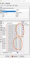
Screenshot JOSM multiple cycle route splits


Split end; route landing on split Node
- We now consider one end of the Node2Node route, landing at the high Node on a highway junction with two Node poles for one logic network Node: one pole for each direction. The crossing highway is a simple road and has no difference between back and forth. This is quite common. Somewhere near the junction, the route splits. One direction lands on one Node pole, the other direction starts from the other Node pole. The other Node2Node routes are simple routes to both ends of the crossing road.
- Put two logical Nodes at the intersections: HiA where the Lo2Hi lands, and HiB where the Hi2Lo starts
- Start the route at the low Node and add the ways up to the split.
- Continue the Lo2Hi branch with proper roles up to the HiA landing Node
- Now you have a choice:
- Method a: Closed loop method
- * Start at the HiA landing Node, add the way(s) to the HiB return Node, and continue to add the ways down to the split/rejoin point, with proper roles
- * Let the other routes land on the first Node they encounter.
- In the end, section HiA-HiB is part of all three the route relations.
- This method guarantees connectivity between all directions of all the routes, but it needs some redundant tagging.
- OR method b: Cluster method.
- * Start at the HiB return Node, and add the ways down to the split/rejoin point, with proper roles.
- * Then create a separate short route from HiA to HiB (Cluster method)
- * Let the other Node2Node routes land/start at the first Node they encounter
- In the end, Section HiA-HiB is a completey separate route relation.
- This method guarantees connectivity by adding an extra relation.
- Methods a (Closed loop method) and b (Cluster method) are equal for rendering and routing, and both pass all consistency checks.
Four routes with split direction branches landing on a roundabout with split Nodes
- We now consider a roundabout with two-way cycleways all around. Four roads with oneway cycleways at both sides land on / leave from the roundabout. There are cycle Node poles at all landing/leaving points, all carrying the same Node number. Of course, all directions of all routes need to have either direct or indirect connections to all the other routes (and to themselves), for visual display and for routing purposes.
- Complicated? Don't worry, it's easier than it looks, once you have mastered the branch tagging for cycling routes. Just pick one of the following methods, both will get you there!
- Closed loop method: closed loop route relations contain the roundabout sections
- First, enter all the network Nodes at the intersections where a route lands or leaves.
- Then create one of the routes with branches for the directions as described above. Let one branch land on the first Node it sees.
- Now let the return branch begin on this same Node. Add the ways of the cycleway roundabout up to the appropriate leaving Node.
- Finish the return branch up to the common ways of the route.
- Do the same with the other three routes.
- Every section of the roundabout is now a member of 3 or 4 route relations. This is redundant, but works alright.
- Cluster method: split end routes; the whole roundabout is a separate route relation.
- First, enter all the network Nodes at the intersections where a route lands or leaves.
- Then create the cluster relation. This is a Node2Node route relation all around the roundabout, connecting all the Nodes with the same Node number.
- Then create one of the routes with branches for the directions. Let the main branch end on the first Node it sees.
- Now let the return branch start from the appropriate return Node. Finish the return branch up to the common ways of the route.
- Do the same with the other three split routes.
- Every section of the roundabout is now a separate member of the cluster relation. This is alright.
