F3DB
| This indoor-related proposal is just a draft and hasn't got wide software support. It should not be used to integrate new data. Instead, use the Simple Indoor Tagging scheme which has got wider software support. |
Definition
"Full 3D Building" (short F3DB) describes a universal approach which combines existing indoor mapping approaches with outdoor 3D modelling of buildings (S3DB).
Background
The two approaches (S3DB and indoor mapping) are similar but not identical. The gaps should be closed using the F3DB approach.
Objectives
- Backward-compatibility
- Simplicity
- Compatibility with standard definition in civil engineering
- Objects can be detailed and built in several steps
- Separately rendering outdoor/indoor structures level by level
- Important parts compatible with Industry Foundation CLasses (http://de.wikipedia.org/wiki/Industry_Foundation_Classes)
- Important parts compatible with CityGML, SIG 3D, OGDC.
- Support of S3DB
Specification and workflow
WORK IN PROGRESS
The F3DB specification is built up by three associated levels of feature sets to describe 2D, 2.5D and 3D data. Beginning with the 2D mapping , it is possible to enrich this data later to get a 2.5D or even 3D description of the building. The following description refers to the 2D specification. Additions, which are referring to the 2.5D or 3D description, are marked separately by (2.5D) or (3D).
General notes
To distinguish between the levels of a building, each way and poi of indoor environments should be tagged with a level identifier like in the following example for the first floor:
The start of modelling
... is either drawing of the building outline using satellite pictures, GPS measurements ... or simply using the existing outdoor data.
If you have the ground plan of the building, you can use it for refining the outline of this building. Information about how to fit such a ground plan in the existing outdoor data can be found under: [1]
Adding of first indoor structures: Indoor Areas
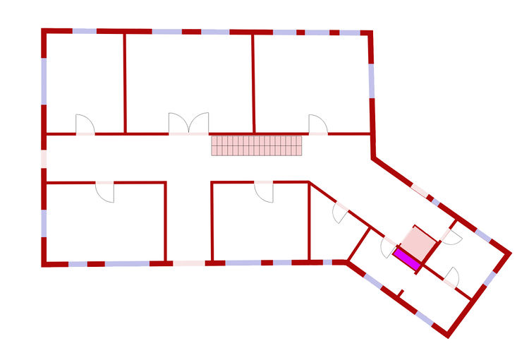
Based on the fitted ground plan all rooms of indoor structures including pedestrian spaces are drawn as ways with following tagging on the top of the existing building outdoor shape:
- indoor:area=* with
- name=* and if known,
- ref=*
Of course you could also use established tags for describing the purpose of an area in detail.
Example: Mapping of toilet room based on the information of the ground plan
Please pay attention to the required level tag 'indoor:level=0'. The assignment of an indoor area to its level is always done by this tag! During the mapping of a building with multiple levels you should apply filters to JOSM. A filter for displaying only elements of the ground floor should look like:
type:way & "indoor:level":"0"
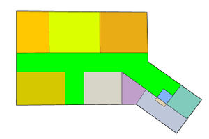 Mapping of each area by use of closed polylines with tagging indoor:area=* = value
More detailed specification according to newest open source standards: ( to be completed next days)
Please note:
The indoor areas have the same points with outline shape of the building and neighbor areas! This is the most important difference between this proposal and older indoor proposals like [2].
Furthermore indoor areas are not describing walls, because there are open rooms without walls, too. Look at this example:
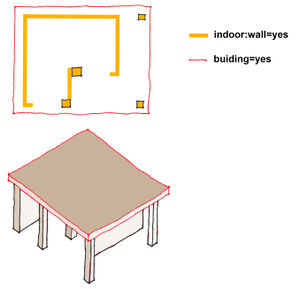 The inner room of this building is not completely wrapped by a wall.
Optional: Zones
Zones are special closed areas without walls or sometimes only with special dividers like crash barrier. Tagging:
- indoor:zone=<name>
Examples: decoration / show / exhibition / gastronomy / waiting_area / artificial_pond / artificial_stream / recreation / playground / smoking
Use: For drawing of special areas like really large rooms, for example an airport with different sections within a single room, e.g. border control, arrival gates, departure gates and so on.
Adding of walls
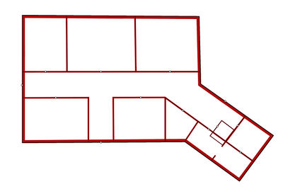
Existing ways with tagging indoor:area=* can be extended to define walls. If the wall of an area as different heights or widths, the way has to be separated to model this.
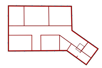
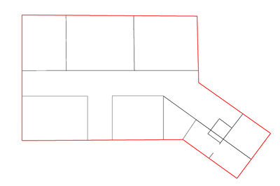 Walls in the building tagging of black lines:
- indoor:wall=yes
- width=*
- height=* (2.5D)
Other possible values:
Look after adding walls:
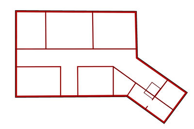 Possible graphical representation on the indoor map after tagging the walls with the key width=*
Adding of Routes and ways
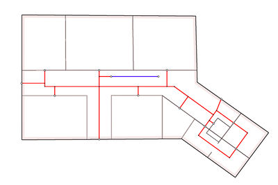
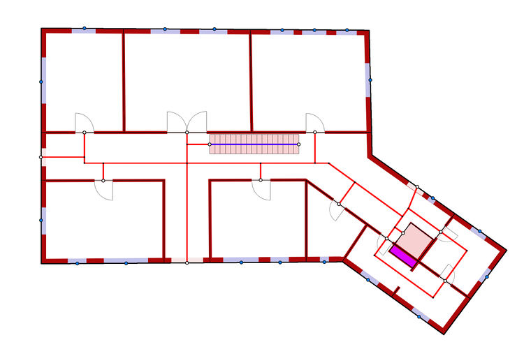
Ways are drawn as lines. The areas are already drawn as surfaces with names.
Routing ways in the building are described as.
- indoor:highway=footway
- indoor:highway=steps
- indoor:highway=ramp
- indoor:highway=elevator
- indoor:highway=escalator
The reasons for prefix: indoor:highway=*
- backward compatibility with Mapnik rendering. (ways are invisible in the OSM main page and don´t disturb on the standard map like by use of old indoor specifications)
- make it easier for indoor navigation (Selection of ways in and outside of building)
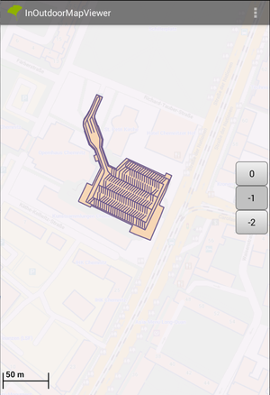
Furthermore there should be indoor roads considered to describe buildings like car pars or underground car parks. Such roads should be tagged in such a way:
First rendering examples are shown here:
Adding of doors
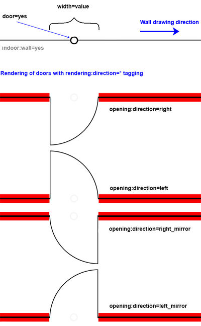
Doors are parts of the wall; points with attributes
- door=yes or more specific, door=* see: Proposed_features/door,
- width=*,
- height=*
- opening_direction=*
Tagging of door direction
Solution A
"Geometric approach". Preferred by the majority of discussants. Absolutely but one need to know the drawing direction of the wall, which is recently not supported by some editors.
For correctly tagging of opening direction for rendering the drawing direction of wall vector should be considered:
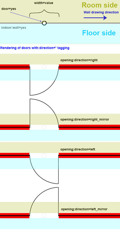
Solution B
note:rejected!
"Floor / Room" approach. Faster but not clearly in some situations (room to room doors).
I stay in the corridor and see the door opens direction floor.
The door is:
- opening:direction=left when the handle is on the left side
- opening:direction=right when the handle is on the right side
I stay in the corridor and see the door opens direction room. The door is:
- opening:direction=left_mirror and when the handle is on the left side
- opening:direction=right_mirror when the handle is on the right side
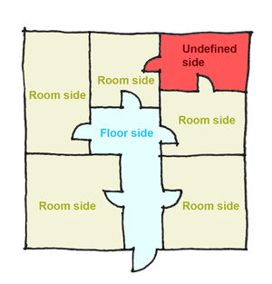
This solution is rejected by the majority of the discussants because of possible conflicts. See sketch below. The "red" area is undefined and can produce rendering mistakes:
Tagging of windows
Windows are, similar to the doors, points in the walls with tagging:
window=*.
width=*
height=*
min_height=*
more details see: Key:window
Stairs, ramps, escalators
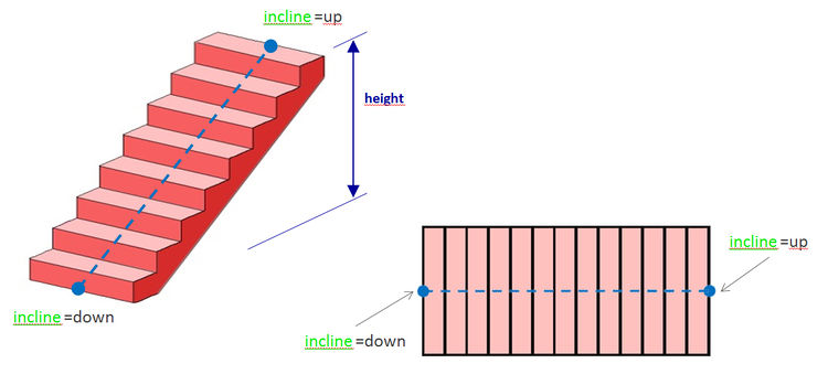
Stairs direction is defined by tagging of start and end point coordinates of the indoor:highway=steps element (or of the sum of succession of elements like indoor:highway=steps - indoor:highway=footway - indoor:highway=steps )
More details with advanced stairs modeling: [3]
The lowest step point should be tagged as:
Analogically:
- indoor:highway=elevator
- indoor:highway=escalator instead of conveying=yes
- indoor:highway=ramp
Rendering mockup 2D
Result after rendering of: walls, doors and windows tagged with:
height=* and steps tagged with:
height=*
Alternatively: possible view of routing and architectonic drawing.
Drawing of roofs
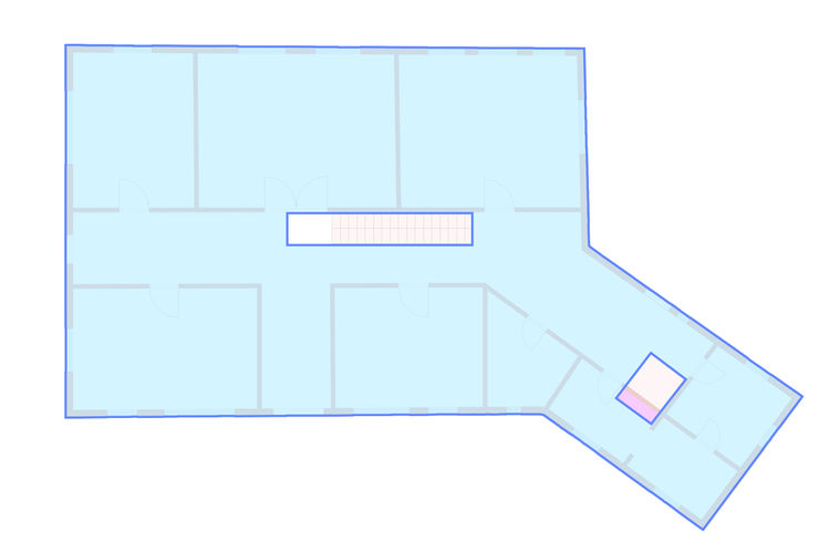
For getting of full 3D model, drawing of roofs with openings for steps or galleries are necessarily.
Tagging:
- ceiling=*
- roof_level=<value>
- roof_height=* means the thickness of the roof
Note:
roof_level=0 means the floor on the ground floor
Drawing of ceiling=yes (blue line) use of relation for drawing of openings.
The openings may be tagged as specific areas with name=* .
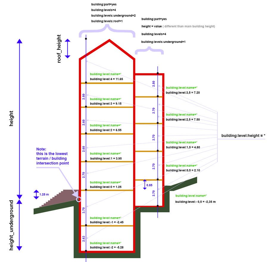
Levels. Building section and definition of height
Tagging:
- indoor:level:number=value E. g.: indoor:level:1=3.95. The value 3.95 means 3.95 meter over lowest terrain with building intersection point.
- indoor:level:name=value Describes the common of internal name of level, e.g.: Basement, 2BS, Recreation Level
Reference point for definition of building height
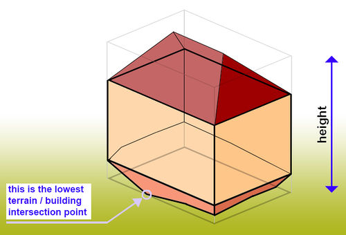
The following sketch shows the position of reference point used for height=* calculation: It is the lowest possible intersection point between building facade and terrain.
Note
It is not necessarily to collect the values drawn in blue color. The height of each level is the result of division of values e.g. 4.th Floor height -3.rd Floor height.
This approach allows especially:
- drawing of indoor walls which are lower than the ceiling.
- saves tagging: no height value for indoor wall means automatically - the wall has the height of the floor.
Roofs
Tagging: roof=yes
The roofs used in S3DB definition are a kind of so called "CSG models" ( see: http://en.wikipedia.org/wiki/Constructive_solid_geometry).
The F3DB uses for modeling the sum of single planar surfaces, so called "boundary representation" ( see: http://en.wikipedia.org/wiki/Boundary_representation).
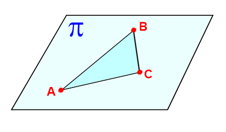
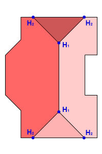
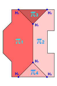
For a clear description of a plane in space (called usually "Pi"), you need three known points:
Therefore, a roof must have three points with elevation data.
The mapper has freedom to decide which three points should have height values, tagged as ele=*
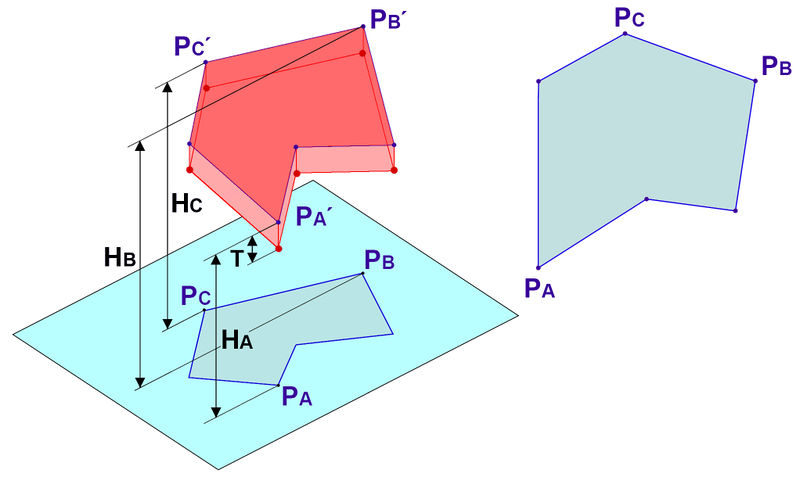
The roof of building is according to this definition a sum of single surfaces. This approach allows modeling of very complicated elements because all 3D objects can be represented as a sum of single surfaces.
Tagging
- Three points on the outline are tagged as ele=*. For example: Pa, Pb, Pc
- roof_thickness=* (The T parameter on the drawing). If there is no information about roof_thickness then T=0
- surface=* or more detailed: surface_top=* surface_down=*, surface_sides=*.
- colour=* or more detailed: colour_top=* colour_down=*, colour_sides=*.
Note:
- Not longer necessary is the tag roof:height=* because the position of the roof outline shape is clearly defined by 3 points with known heights.
Pa´, Pb´, Pc´= points in 3D space.
Ha, Hb, Hc = corresponding heights of these points in space
Pa, Pb, Pc = top view ot these points
Tagging of roof angle
- inclination=* (See Alpha parameter on the drawing) ; defined as surface consists of three points in space: The lowest point of the roof and his neighbor on the left and right. Have the neighbors the same height value (they lie on a straight line) the next possible point with another height value. In the most of cases is the lowest point and his one neighbor easy to define (it is a gutter height).
or:
- ele_roof=* is distance between this point of roof shape and lowest terrain / building intersection point used for description of all 3D building elements (see the drawing with the building section in the part below).
For planes consisting of triangles is the inclination definition often complicated, because one need to know all height values of shapes in 3D. For such purposes you may use sketches from 3D modelling programs which allows the query of the height values of 3D points.
In such cases it is more easy to describe the roof surface in space (Pi) by definition of any three points which are not on a straight line.
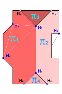
Use case below shows the practical difficulties of triangle approach:
One have to calculate exactly the height values of H5 and H6 for getting of Pi1 and Pi2 as a flat plane.
The roof can include openings (multipolygon with relation), similar to the ceiling.
Note:
roof_thickness should be considered by calculation of exactly architectonic models of buildings. The definition comes from architectural building code and should in future help with semi automatic import of 3D building models.
Suggestions
Please put here your ideas and suggestions!
- Drop indoor: for indoor:highway=* prefix, add indoor=yes to elements instead. "backward kompatibility with Mapnik rendering" is not a good reason, just because default style changes at glacial pace it is not a good reason to create a separate set of tags. "make it easier for indoor navigation" would work as well with indoor=yes. Adding indoor prefix will make processing this data harder for everybody and everything (starting from editors) Mateusz Konieczny (talk) 14:38, 18 July 2014 (UTC)
- What do you think about renaming of roof_level=* -> roof:level=* and roof_height=* -> roof:height=* in #Drawing_of_roofs? --Edward17 (talk) 21:32, 20 July 2016 (UTC)
Question and Answers
Links
Modeling examples:
- F3DB_mapping_examples (Note: page in work. Be patient. Content comes \september 2014)


