Stairs modelling
The page describes tagging stairs for modelling stairs in 3D.
Use cases: F3DB, OSM-4D. This concept enables (regardless of the 3D modelling in F3DB) better 2D rendering of stairs on common 2D maps.
Background
OSM maps are more and more detailed. Large stairs, mostly located outdoors are drawn as simple midlines in OSM maps. More and more users are unhappy about that. This mapping concept allows development of more advanced rendering techniques for 2D maps. Additionally, such stairs will be able to be displayed as 3D models.
Definition
In order to allow a more precise mapping stairs should be drawn (and supported by rendering software) in 3 different ways:
- middle axis vector or polyline
highway=steps, withwidth=*and optionallyheight=*or - middle axis vector or polyline
highway=stepsand start and end stairs polyline or - as a combination of middle axis vector or polyline with the closed
area:highway=stepsand optionallyarea:highway=footway.
(Compare with drawing of rivers as area in OSM)
Parameter
| Key | Description | Value |
|---|---|---|
width=*
|
Width of steps | m |
step_count=*
|
Number of slopes | Integer |
height=*
|
Total height stairs | m |
material=*
|
Material of the stairs | See Material library |
steps_type=*
|
Type of single-stage | Sehe Form library |
handrail_height=*handrail:height=*
|
height railing | m |
handrail_form=*
|
The form of the railing | See Form library |
handrail:left/right/both/center=*
|
railing on the left/right/both/center side of the stairs | yes/no |
stairs_thickness=*
|
Thickness of the stair construction | m |
stairs_start_angle=*
|
Rotation of the bottom step to upgrade axis | degree (°) |
stairs_end_angle=*
|
Rotation of the top step to upgrade axis | degree (°) |
depth_step=*step:depth=*
|
Depth of a single stage | m |
height_step=*step:height=*
|
Height of a single step | m |
| in area-relation: role:lower | Polyline, start line irregular steps | Polyline connected with highway=steps via relation |
| in area-relation: role:upper | Polyline, end line irregular steps | Polyline connected with highway=steps via relation |
| in area-relation: role:lateral | Polylinie, Außenkante unregelmässiger Treppe | Polyline connected with highway=steps via relation |
stairs_inline=*
|
Polylinie, Innenkante unregelmässiger Treppe | Polyline connected with highway=steps via relation |
stairs:type=*
|
see Relations/Proposed/Area#Area-steps, steps which are wide and/or irregular for the area-relation model of steps.
Parameter description
Type of staircase
Used for 3D purposes only.


Stages with offset
Used for 3D purposes only.
All stages can have offset.
Examples forming of stages for 3D rendering:


Railing position

Position of railing:
Start and end angle stairs
Sometimes is the start of end angle of stair steps not at right angle to the ascending direction.
In such cases add tags for initial slope of first and last point of steps:
stairs_start_angle=*value in degrees. Calculation of angle see sketch below.stairs_end_angle=*value in degrees.Calculation of angle see sketch below.
 Anfangsneigung Treppe (alpha s) :Treppe im Punkt S, Endneigung Treppe (alpha e) Treppe im Punkt E
Exkursion rendering
A staircase with many wrinkles and without stairway landings is rendered as in the following example:
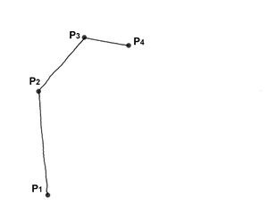
highway=steps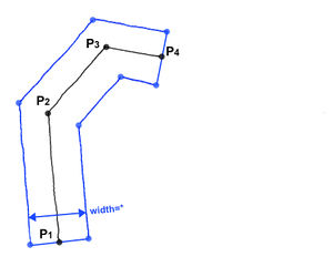
width=value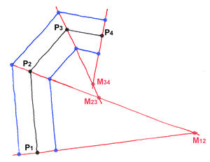 rendering machine calculates section points M12-M23-M34 by use of angle bisectors.
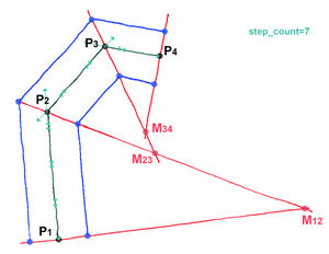
step_count=7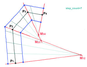 rendering machine divides polyline P1 - P2 - P3 - P4 in 7 sections of equal length.
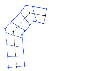 Sketch: final result after rendering.


Mockup rendered example:

Importance of height for 2D rendering
For plain 2D rendering under use of width=* is it not important to know where the up and down point of stairs is unless:
- Start and end of the staircase is located one above the other.
- Polyline of the staircase has intersections.
Example: two possible rendering results of stairs with intersections:


A staircase with stairway landings.

Möchte man Treppen mit Zwischenpodesten erhalten, was für längere Treppen überwiegend Standard ist, so muss man einen OSM Grundriss wie in unterem Beispiel konstruieren: Anstatt einer Polylinie mit mehreren Zwischenpunkten wird pro Relation eine miteinander verknüpfte Abfolge von Treppen (S) und "Podestlinien" (P) konstruiert.
Depth of the single step
depth_step=*, (Ds, necessary for 3D purposes only)

Start- and end point
Thus, the stairs can be interpreted properly in 3D, the bottom and top of the stairs must be marked:
Start- and end line
Stairs with complicated geometry can be drawn, by drawing of uppermost and lowermost outer edge of the stairs as a polyline. Tagging of the lowermost line: steps:startline=yes the uppermost: steps:endline=yes.

These two lines are connected together. The connector line is the midline of stair geometry tagged as: highway=steps. This line should still be used for routing.

Result after Rendering (mockup)*

- Neccesary Assumptions for the renderer, which can be developed based on this proposal:
The starting point of the polyline stairs:startline=yes is connected to the start point of stairs:endline=yes.. The line is divided into n-step sections for rendering. The same with the end points of polylines stairs:startline=yes andstairs:endline=yes
The approach solves problems arise when drawing large, complex stairs, because of differences between logical connectors for routing (graph network) and the desire, to reflect reality.
Design options
A. Both polylines have the same number of nodes.
Zwischen den entsprechenden Nodes beider Linien wird die Anzahl der Stufen gleichmäßig aufgeteilt:

- Stairs:startline=yes yellow
- Stairs:endline=yes green
- Treppenvektor,
highway=steps:rot (Start und Endline werden beliebig mit dem Treppenvektor miteinander verbunden) - Verlauf der Stufenkanten nach dem Rendering:schwarz
Der Ansatz basiert auf den in der Kartografie bekannten Höhenlinien. Die technische Schwierigkeit: hier könnten Selbstverschneidungen auftreten.
B. Both polylines have a different number of nodes.
In diesem Fall werden die Endpunkte beider Linien miteinander verbunden. Die einzelnen Punkte der Linie die mehr Punkte besitzt, werden über das Kriterium der kürzesten Entfernung mit den Punkten der zweiten Linie verbunden.


Weitere Gestaltungsbeispiele:

Special nodes for advanced modeling
Rendering the stairs can sometimes lead to an undesirable result if one draw start and end line with different number of nodes:

In particular, this can result in an undesirable geometry of lines after rendering:

drawn outline shapes

internal triangulation by renderer

unclean renderer output

result optimized by use of tagging solution described below.
If you want to avoid this and get the wishful result, the start and end line must be divided
by use of additionally tagging of points they should be connected corresponding to their position with:
If the real height values are known, you can use ele=* ( 3D)
The number of this points must be the same for start and end line!
(See sketch below: blue lines connect points that have the same tagging schema)

This tagging should be taken into account by the renderer.
Result mockup:

Outline and Inline
An "outline" multipolygon with tagging area:highway=steps, draws the irregular outer surface of the stair from top.

Therefore is it possible to combine several steps and footways as connected elements in ONE outline shape:

The surface after rendering:

Examples
Mockup rendering of a sequence of highway=steps and highway=footway with the same width=*:
 Classical OSM 2D representation

 Example: Rendering of a curved platform in OSM-4D
Combination of several connections within one outline:
 stairs outline (Outline shape)
 Stairs and footway lines.
 Tagging
 Mockup: result after rendering
Roof direction
For right 3D interpretation of stairs one need the lowest and heighest point of steps. There are following possibilities:
Describe the lowest point of stairs as: "lowest:point=yes" Describe the highest point of stairs as: "highest:point=yes"
How to draw stairs for wishful steps look
Do we want to achieve the following stairs shape in 3D:

we must add an additional break point of the polyline - a step further than the start of the turned steps:

Dadurch bleibt der Stufenverlauf links senkrecht zu der Verlaufachse ohne Notwendigkeit der Parametrisierung. Analogously, for example, a half-turn staircase are drawn:

Example modeling of barock stairs
The staircase consists of three outline areas; two steps areas and one footway area:
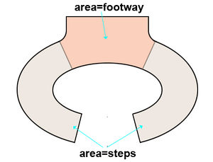
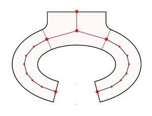 Steps (black midline) and footway (red midline)
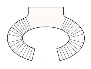 Rendering mockup


