Roof modelling
This article refers mainly using of Potlatch and aerial images like Bing. Apart from details in the handling of Potlatch are the discussed methods also applicable:
- In other editors like JOSM and Merkaartor or iD
- With aerial images other than those of Bing.
Tips
Don't forget to add (in the left panel) a building tag to the outline after drawing!
You should only use the most detailed zoom level when drawing buildings.
In Potlatch 2, the background imagery layer should not usually be "dimmed", as it can make interpreting the images harder. To turn it off, select Background and uncheck the "Dim" checkbox:

Drawing at the base
For buildings which are rectangular and where two sidewalls are visible on the imagery, one can draw a 2-segment line along the base (JOSM: a), rectangularize (JOSM: q) (iD: q), then continue drawing with angle snapping on (JOSM: a a). This sometimes works with non-rectangular buildings too, so long as invisible corners can be extrapolated from a known wall.


Drawing at the roof
In many cases, the roof is the most visible, or in fact, the only visible part of a building. The following approach works well for many buildings.
- Draw along the outline of the roof, apply rectangularization (e.g. JOSM 'q' key) if so desired.

- After the roof shape has been drawn, it should be moved to match the location on the ground level. To accomplish that, move the way until the corner of the roof touches the best visible corner/edge of the building.
- Due to perspective, the roof is not necessarily the same size as the base, and the polygon may need to be enlarged/shrunk a little. (JOSM's Extrude tool can help here.)


In this picture, the moving direction was visible very well, but if it isn't, look at the neighboring buildings to get a sense of the direction. Do note that image providers stitch images (even of the same day), making the oblique angle suddenly shift midway in another direction, sometimes even within a building.

Multi-section roof
When a building has multiple sections of roof, or an interior free space, the same roof-drawing approach can be used, but repeated for the different levels of roof.
- Draw along the highest level's roof edge(s).

- Move the outline to the nearest lower visible level; this can very well be more than one story down.

- Repeat, i.e. draw roof edges of the next level

- Move all polygons, current and those originating from higher levels, further down.

If there are any free space sections (e.g. courtyards), create a multipolygon. (In JOSM, first select the outermost polygon, followed by all courtyards, then use Ctrl-B.) All other roof polygons can be tagged as per Simple 3D Buildings with building:levels, etc.
About the logic of building making
Buildings are often designed and built based on the right angles. Parallel and perpendicular walls simplify and cheapen the construction; they allow the use of standardized components and simpler manufacturing and installation (e.g. roof construction). It's also convenient for the tenant to have their squarish furniture fit the right-angled corners. However, not all buildings are constructed on a right angle plan. Examples are old buildings, architect's choice to avoid the right angle for a more visually striking facades, and limitations set by the surroundings, such as corner buildings when two conjoining streets are not at a right angle.
Therefore, when drawing buildings from poorer quality aerial imagery, it is wise to assess whether each building is likely to have right angles on the ground, or whether the corners possibly aren't such. Prior knowledge of the settlement's history, and of the architect's style of choice, can be valuable when making this assessment.
- Please note: Buildings often have symmetry axes!

Image above is an examples of 8x and 2x symmetry.
- Note: JOSM PlugIn CADTools has mirror copy function!
Function "make rectangular"
Potlatch 2 (and iD and JOSM) has a built-in function with which you can make the closed polygon perpendicular. For relatively simple building forms, you are very likely get good results with this feature, even for buildings with lots of corners:

Note: JOSM and iD editor shortcut for making rectangular is Q
Tricks
Drawing of many identical buildings.
Potlatch2: has not yet the "copy" - "paste" function, but you can get this result: Just use option "create parallel way", and make a copy of drawn building outline. If you zoom highly on the building, you can draw a copy of which is practically identical to the original. In many settlements you can often see the buildings which have identical geometry and stand parallel to to each other. Is the quality of the aerial photographs partially not good enough, you can trace the best visible building as accurately as possible and work with this sample building.
JOSM: Ctrl+D. Using PlugIn CADtools are more copies, e.g. rotated possible.
iD: Ctrl+C, Ctrl+V. Many times Ctlr+V results in many copies.
B. Drawing of complicated building outlines.
Potlatch2 still has not expanded CAD functions. But you can do good template for a relatively precise interpretation of the building outline through the drawing of many construction lines (using the command: "create parallel way, shortcut P"):

Practical use: We draw a large outline along the longest sides of the building and convert it into a rectangle (option "make right angles") around. We copy the rectangle to as many construction lines (which by definition are parallel and perpendicular to each other) as necessary. The construction lines (rectangles), are moved to the outer edges of the roof surface to trace the outline shape:

After tracing we remove of course all the construction lines... Result


B.2. "Straighten" neighboring exterior walls of buildings by using of command: "straighten way"
Situation: Some adjacent buildings (as an example here downtown, old buildings). We see the outer walls of the buildings are in fact a straight line, but in the drawing shape it is "almost" straight. To straighten these edges, we draw an auxiliary line, touching all points of this curve. It is necessary that at least one endpoint is outside this line to straighten the walls:

Use function: "straighten way" As a result, the outer edges of the houses are straightened.

Buildings after execute of order: "straighten way"

Result after deleting of helpline:

Note: the same function in JOSM is the shortcut: l the same function in id is the shortcut: s
B.3. "Straighten" not neighboring exterior walls of buildings by using of command: "straighten way"
- The problem is clear. Using of orthogonalization made one node wrong positioned:

- Solution: Drawing of straighten line with begin AND end on the proper drawn corners of building:

- Result after execute "straighten line":

C. Drawing of long "snake buildings" in Potlatch2
Tracing the long blocks of flats which are built along a polyline with many changes of direction, is often a source of error:
Many users zoom in so that you can see the whole building on the screen and draw the outline shape, making the accuracy low. It is especially difficult to draw the right angle on the short sides of the building.
You can work around it by drawing a double line in Potlatch 2:
We draw on the best long, side of the building and make a copy of the polyline with the command: "create parallel way", (shortcut P).

We get a second polyline that is "parallel" to the first. But above all relates to the corresponding endpoints of the two polylines at right angles. We extend the polylines so that they touch. By holding down the Ctrlkey we activate both polylines.

Then we click on the button "merge ways" ![]() and both of the polylines connect to form a way which is then converted to a building:
and both of the polylines connect to form a way which is then converted to a building:

Note: the same function in JOSM is the function: PlugIn Parallel way (Shift+P) makes parallel copies of ways. No such function in iD!
Drawing and rotation of ellipse with JOSM
For this purpose you have to load JOSM PlugIns CADTools and ShapeTools
PlugInCAD Tools allows generating of ellypse in that way:
1. Draw a rectangle describing an ellipse on the map. Activate this shape.
2. Start CADTools (Tools -> CADTools)
3. Click on the button: "From polygon to ellipse". Info: the number of segments (segments= <>)
will be four times larger. We put in the window as if the number of segments on a quarter of the ellipse. Click on OK.
The result is today saddled with programming error: ellipse will be drawn in a horizontal or vertical position. It should be now rotated on the correct angle.
4. Use for this the plugIn "Shape Tools" that can be find here: https://github.com/asrianCron/ShapeTools/releases/download/alpha/ShapeTools.jar this PlugIn allows you to rotate any element of the specified angle.
Example
Drawing midline of the ellipse

Drawing outline rectangle...

...finalize rectangle

Choose CAD Tools and put the number of segments. Enter.

Result has wrong rotation. You have to measure the angle ( steps 1,2,and 3=activating of "Shape Tools" )

Insert there the measured rotation angle value. Enter.

Result: Now you may add your key and values for the ellipse.

note: this is OSM way nr. https://www.openstreetmap.org/way/440287560
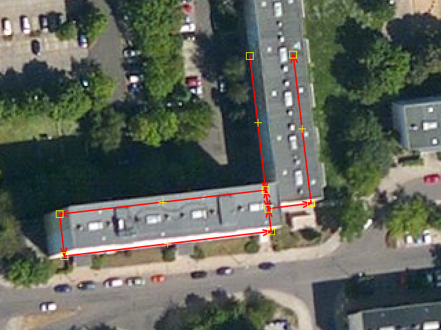
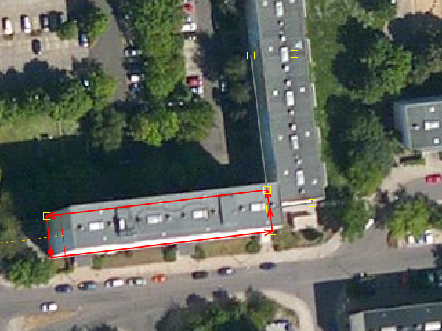
Typical errors in the interpretation of roof geometry from aerial images
Outline in wrong location
The user has drawn the roof shape carefully,

but has then moved the way to touch a wrong, false corner of the shadow of the building. (This is a quite common error.)

The shape should have been moved all the way to touch the real intersection of the wall corner and the shadow edge, as in this drawing:

Incorrect interpretation of double pitched roof
When the roof is sufficiently pitched, there can be a visible corner in the middle of one edge. The wall is nevertheless straight here - this corner does not exist in the building outline.

Incorrect interpretation of pitched roof
Sloped roofs can be tricky even for an experienced mapper, because the angle of the roof can easily go unnoticed. If that happens, the building shape is drawn as follows:

If one is not carefull and just selects the "make rectangular" function, the result looks like this:

Quite often this error is only evident only after the previous step, when the edge of the now oblong building shape, and the corresponding edge of the shadow aren't parallel - assuming the mapper is lucky enough to see the edge of the shadow well enough.
Correct procedure:

- First draw the both visible edges of the walls at the ground level: a way connecting nodes A-B-C
- Move this line "upward" along the building wall, until it touches the corner of the ceiling best visible in the image (Node F)
- Now you can add the edge from F to G (the roof edge is horizontal there), and then from G to Y.
- Finally, move the way back to A-B-C-D.
Modelling of outlines of building with different heights
The correct tracing of buildings with different height components is particularly problematic. This is is especially true if the plan is also covered by adjacent buildings or trees. Sometimes only a tedious procedure as described below is possible.
1. The highest part of the building is drawn.

2. The traced outline is moved downward so that it touches the adjacent lower-lying area.

3. The area, which was traced first, usually gives us the location of additional, hidden points P that we need for construction of the second surface.

4. After tracing, the two areas are merged and moved down based on a visible corner of the floor plan.

Drawing of building outlines of buildings on slope
If a building stands on very uneven terrain,

tracing the outlines of the buildings at the ground level leads to erroneous results, if used as a template for oblique aerial photographs:
 Blue arrow: View direction of the camera.
In such cases only the roof shape should be drawn as the building outline and not the geometry of the intersection lines between the building outline and terrain:

After construction of roof outlines, move them so that the building is properly placed in relationship to the street.
In case of free-standing buildings without reference to the street, the position error is reduced by a shift of half the distance between the lowest and highest position one as the outline for on the aerial photograph visible corner building on the site selected.

Drawing of building outlines based on low resolution aerial images
If in the background of OSM there are only roughly detailed aerial photographs, the tracing of the buildings is difficult because the size of the building is nearly the size as the icons of the design tools. This is of the greatest difficulty, if one wants to draw precisely: The graphical representation of the tools and nodes is simply too large for the objects in the small scale. The approach described here deals with this problem in rectangular buildings. The technique is laborious and slow, but gives relatively good results.
 - Traced, the L-shaped building in the middle.
In the first step, a long construction line is drawn which is parallel to the longest visible wall of the building. The line should be longer than the building. This allows better assessment of the building orientation.

Draw a second construction line parallel to the first (Potlatch2 shortcut "P" )

At the ends of the two parallel lines a straight line is drawn which connects the two endpoints of the lines. The line is perpendicular to both vectors previously drawn.

Use button "create parallel way" and draw another (necessarily for construction) lines perpendicular to the first two lines drawn and placed at the outer edges of the building.

Additional long construction line in the middle is drawn:

At points where the lines intersect with each other, nodes are added. With the tool "straight way" one line must be straightened after the other ... (a weakness of the potlatch is a slight displacement of the points which we have added to the nodes on the paths)


When all lines straightened, you can start drawing the outline of the building:


Result:

Correction of perspective distortion
On the buildings on aerial photographs from low altitude (usually higher resolution) perspective distortion is often seen. This means that the correctly-drawn outline of the roof is larger than the building outline.
At first glance, you hardly notice this:

Only the tracing of corresponding vertical outside edges of the perspective view (reduction to the ground plan) would make this visible:


Since the building roof and floor plans are similar, you can use the tool "create parallel way" to create the right plan.


Practical approach:
- Trace roofline

- The roof outline is moved to the ground plan
- A matching corner (on this picture the lower left corner of the drawn polygon), is placed correctly on the aerial photograph.
- A construction line parallel to the (right image in this example) the outer edge of the building is drawn and placed on the outside edge of building on the aerial photograph:

The outline polygon is drawn smaller with the "create parallel way" tool:

Thus, the degree of reduction is clearly visible, the detail being greatly magnified.
(Therefore, the temporary construction line is shown, at higher zoom levels the detail image disappears).
- The newly drawn (except this picture right) outer edge of the polygon is copied
to lie on the half-way between the construction line and the source polygon.

- The original polygon and line construction is deleted, and the new plan polygon shifted to the right place.
Result:

Attention! This method is an approximation. You get absolut accurate results only by construction of the central perspective:

Correcting wrongly assembled roof images
Apparently, the main objective when Bing combines its aerial photographs is the alignment of the streets. Therefore, combining multiple photographs taken from different angles into a single unit is done in such a way that the street is clearly visible. This means there are places where the roofs of buildings appear to be "coming apart":

The fact that one part of the roof does not fit into the other does not mean the land on which a building sits is not properly aligned. Therefore, individual roof sections are modeled separately and assembled in the ground plane.
Steps:
- Draw the construction lines of the first part of the roof. Make the construction lines a little bit longer

- Move the construction lines to the ground level.

- Draw the construction lines of the second part of the roof.

- Move the second group of construction lines to the ground level:
You see that both groups of construction lines overlap, so You can combine them into an area.

Result:

Drawing of big, rasterized areas
 Existing OSM map - drawn without raster.
City Planners often use a grid: It makes planning and realization of construction projects in big areas easier. In OSM the reconstruction of the main construction grid helps with tracing of buildings, roads and parking lots. In this way one avoids the inaccuracy that arises when one works only with short construction lines. The redrawn maps look even more professional: People recognize with the eyes slight deviations from parallelism of the lines (some people perceive the little difference of 0.5 °!)
 First construction step: Identification and drawing of construction axis. This is question of practice: The longer the line, the more accurate it is.
 The axis should be duplicated to construct relevant bodies (roads, building edges), etc.
 Analogously to the previous step: drawing of axis perpendicular to the first construction axis..
 We see all the inaccuracies when zooming.
 The inaccuracies will be corrected
 Map before correction
Result after correction.
In the upper left corner of the picture below we see a building at the cross plan. This building was also drawn more precisely by using of construction raster ( due to a rotation of 45 ° to the construction grid).

Use of raster lines with auxiliary points
The technique described in the previous section is difficult, because You need to put manually at every point where two construction lines intersect an auxiliary point, or try to reach the intersection point of both lines at high zoom level.
It is smarter, after drawing of all construction lines with one direction, to draw the first "vertical" line with all intersection points. After drawing of this line, simply multiply them at all necessarily places and use for drawing of building outline.
 starting situation.
 First line construction.
 Last line construction.
 Begin with the first vertical construction line
 finished VERTICAL construction line


 drawing completed.
 rendering complete