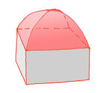
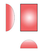
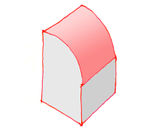
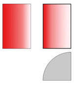
OSM-4D/Roof table
|
This page is the working version and currently not updated! (But as of 2023/11 it currently contains more examples/suggestions for "OSM tagging values" than the German page.) For latest details see polish or german version. |
This page was created by: Marek Strassenburg Kleciak, Kendzi
Note: This page is under construction! The definitions are constantly updated. As this page has gotten very long, the subtypes may be broken out into separate pages.
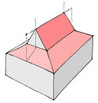
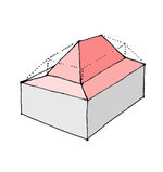
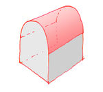
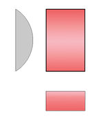
This page collects a list of 3D roof forms and is the part of OSM-4D-definition and as this part of the 3D building-definition.
The 3D roof forms are currently supported (visualization) by JOSM PlugIn Kendzi3D.
"Implemented:<Yes/no/soon>" means implementation in Kendzi 3D plugIn.
NOTE: For the correct application of this schema, the building should be marked tag roof:shape=3dr
Note
The total building height (H) is the same as defined in the specification S3DB.
This parameter is not included in the description below (Parameters), because it applies to all roof shapes.
Flat roofs
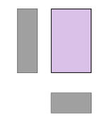
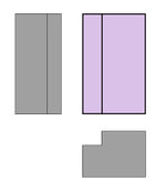
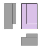
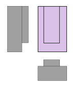
| 3D View
/ Top view + Sideviews |
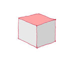
|
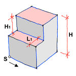
|
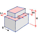
|
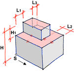
|
|
|---|---|---|---|---|---|
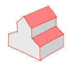
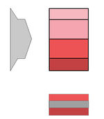
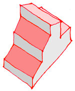
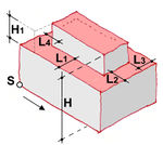
| Numeric Type (3dr) | 0.0 | 0.1 | 0.2 | 0.3 | 0.4 |
| Human-friendly Type | flat | flat_with_terrace | flat_with_two_terraces | flat_with_three_terraces | flat_with_four_terraces |
| Parameters | height=*
|
H, H1, L1 | H, H1, L1, L2 *.a | H, H1, L1, L2, L3 *.a | H, H1, L1, L2, L3, L4 *.a |
| Restrictions | none | L1< depth | L1< depth, L2< width | L1< depth, L2+L3< width | L1+L4< depth, L2+L3< width |
| Implemented | yes | yes | yes | yes | yes |
| Tagging | 3dr:type=0.0
H -
|
3dr: type=0.1
H:
|
3dr: type=0.2
H:
|
3dr: type=0.3
H:
|
3dr: type=0.4
H:
|
| Comment | Applies to all floor plans, including courtyards | Applies to all floor plans, including courtyards | Applies to all floor plans, including courtyards | Applies to all floor plans, including courtyards | Applies to all floor plans, including courtyards |
(*a) = if only L1 then all other L parameters = L1
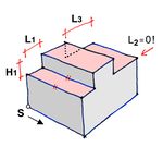
Flat roofs with structures: other notes
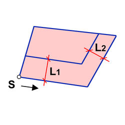
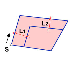
Top view: Behavior of roof type 0.2 with an irregular square
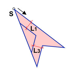
The starting point S where the outline begins, and the direction of the building outline, determine how the roof is interpreted in 3D:
| Outline drawn counterclockwise | Outline drawn clockwise |
|---|---|
|
|
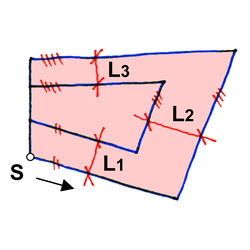
Outline of an irregular quadrilateral:
Top view: Behavior of the roof type 0.3 as an irregular quadrilateral.
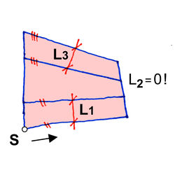
Omitting a parameter on any layout
Top view: Behavior of the roof type 0.3 if the parameter L2 is not entered.
Concave floor plan:
Roofs with one sloping face
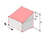
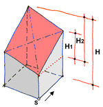
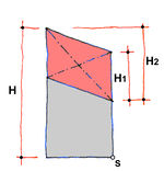
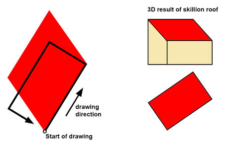
Roof direction is defined by the first point drawn and direction of the outline. The first two points drawn are the lowest points on the roof. The angle of roof inclination is perpendicular to the first two drawn points and goes to the top.
Note: This is the definition specified by this page, some renderers may use other definitions. Please check the results of other definitions such as Kendzi3D.
Attention: H1 means still the difference between height=* and roof:height=* !
see Simple 3D Building: [1]
(*a) = No H3 required, as it can be derived from H1 and H2 given that the roof is flat
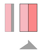
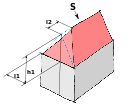
Roofs with 2 faces
(*a) = if no L1 then symmetry: 2xL1 = width
(*b) = if no L2 then symmetry: L2=L1
(*c) = if only H1 then H2 = 0.5xH1 , L1=0.5 x width
(*d) = if no L3 then L3=L2
Note: How to tag roof:orientation for roof:shape=side_hipped and similar roof shapes?
This should be self explaining:
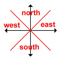
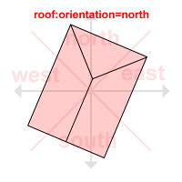
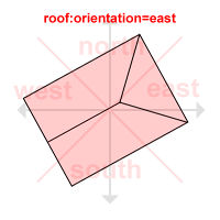
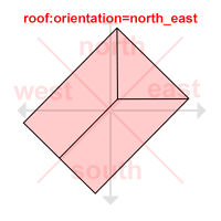
This tag should be added for roof shapes:
- flat_double_terraced
- flat_triple_terraced
- skillion_diagonally
- side_hipped
- double_skillion
- triple_skillion
- corner_saltbox
- triple_saltbox
- round_skillion_cutted
- round_skillion_double_cutted
(*a) = if no L1 then symmetry: 2xL1 = width, if no L1, L2 then symmetry: 2xL1 = width, 2xL2 = depth
(*b) = if no L1 then L1 = width
(*c) = if no L1,L2 then L1 = L2 = width. If L1+L2> depth then L1=L2=0.5 x depth
(*d) = Only three heights neccesary because the lowest height H, is the defined facade height.. H>H1 and H2>H3
(*e) = Possible subtype when H<H1 and H2<H3
Roofs with 2 Faces. L and T type
Buildings on the corner of 2 streets in the closed row of houses have often gabled roof shape which is difficult to generate only by use of roof:shape=gabled.
For this geoemtry I suggest the description roof:shape=L_gabled See example:
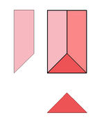
Roofs with more sloped faces
Subtype 3
Examples: 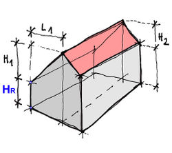 3.0 basic.
 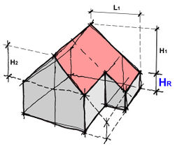 3.0 free outline.
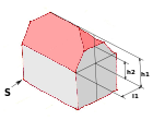
Subtype 4
(*) If symmetric, then only L1, L2 necessary
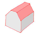
Type 4.2 has, depending on the values of the parameters, sub forms which are not "mansard" roof:
Subtype 5
- Valid only for rectangular shapes!
Subtype 6
Subtype 7
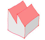
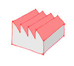
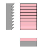
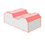
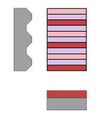
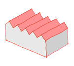
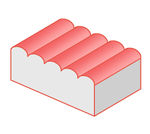
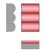
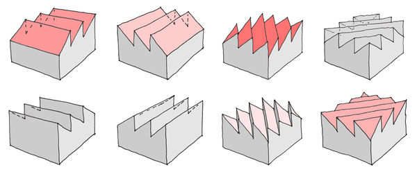
This subtype describes roofs with repeatable geometry. There are at the moment 5 repeatable geometries.
- Simple saw form
- Trapezoidal shape
- Double inclined saw form
- Semicircle
- Wave
The last, 3. number below "n" describes the number of repeat.
Inversion and half end
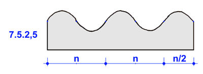 Syntax 7.m.n,5 means the half end of the "wave"
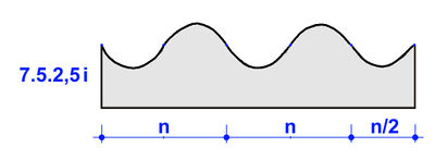 Syntax 7.m.ni mirrors the shape
Subtype 8
Subtype 8 describes
8.A
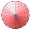
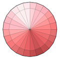
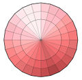
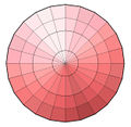
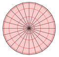
Rotation bodies based on round / regular polygonal ground view. In the default visualization the circle is divided into 24 segments.
| 3D View
/ Top view + Sideviews |
|
|
|
|
|
|---|---|---|---|---|---|
| Typ | 8.0.1 | 8.0.2 | 8.0.3 | 8.0.4 | 8.0.n |
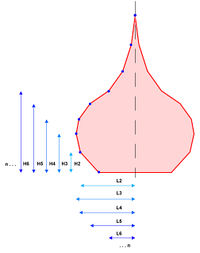
| OSM tagging value | cone | mansard_cone | double_mansard_cone | triple_mansard_cone | onion |
| Parameters | H1, D1 | H1,H2,D1, D2 | H1,H2,H3,D1, D2, D3 | H1,H2,H3,H4,L2,L3,L4 | Sehe Beispiel oben:
Querschnitt |
| Description | Ebener Verlauf | 1 x Knick
in dem Dachflächenverlauf |
2 x Knicks
in dem Dachflächenverlauf [2] |
3 x Knicks
in dem Dachflächenverlauf |
n x Knicks in dem Dachflächenverlauf
z.B Zwiebelkuppel |
| Restrictions | |||||
| Implemented |
8.B
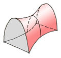
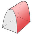
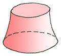
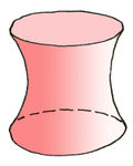
Surfaces of higher degrees
| 3D View
/ Top view + Sideviews |

|
 .. .. 
|
|
|

|
|
|

|
|
|---|---|---|---|---|---|---|---|---|---|
| Type | 8.1 | 8.2 | 8.3 | 8.4 | 8.5 | 8.6 | 8.7 | 8.8 | 8.9 |
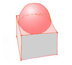
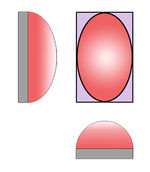
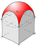
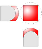
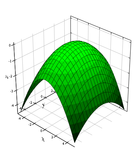
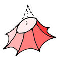
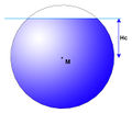
| OSM tagging value | hyperbolic_paraboloid | parabolic | hyperbolic_tower | elliptic_hyperboloid | ellipsoid_cutted | elliptic_paraboloid | tent | geodesic_dome | spherical_cutted |
| Parameters | H1,H2,H3 | H1,H2,L1,L2,ResolutionH, ResolutionV | H1,D1, Twist, ResolutionH, ResolutionV | H1,D1,D2,ResolutionH, ResolutionV, Twist | H1, ResolutionH, ResolutionV, *a | H1, ResolutionH, ResolutionV, Twist *a | H1, D, alpha, ResolutionH, ResolutionV, Twist | Type=
<dodecaeder,ikosadeder, triangles:value> value=<number of triangles> ,*b |
height=value
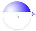
(height of middle point of the sphere), radius=<value> (radius of the sphere) cutting:sphere:top=<value> Hc - Horizontal cutting plane of the sphere on the top or: cutting:sphere:down=<value> Hc - Horizontal cutting plane of the sphere down |
| Description | Sehe: [3]
Any floor plan possible |
If H1=H2 and L1=L2 then
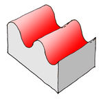
A horizontal parabolic cylinder (see pict right) Any floor plan possible |
Often used in industry | The same mathematical definition
like 8.3 but not cutted in the middle |
tent surface | Geodesic dome, | just a sphere | ||
| Restrictions | no negative values | ||||||||
| Implemented | no | no | no | no | no | no | no | no | no |
(*a) clarify: are this parameters enough?
(*b) nr of triangles=20*n*n or 60*n*n. For understanding of details see page of Werner Brefeld: [6]
- Twist -rotation along z axis. Example see: [7]
- ResolutionH : number of segments of floor plan (when change to regular polygon with n sides wished)
- ResolutionV : number of segments of building height
Subtype 9
Subtype 9 describes the so called generic shapes.
The assumption is that all roof faces of the building start at the same height and have the same inclination. These roof areas can be generated on any floor plan.
This method is particularly convenient because very few tags can describe common roof geometry for large, complex roofs.
Tagging Proposal
| Attribut | Value | Description |
|---|---|---|
| building | yes, * | just building.. |
| 3dr:type | e.g. 2.0 | Describes roof type. E. g. 2.0. Tagging for the quick manual input can be supplemented with the description of the dormers. Extended version can looks like 3dr:type=2.0.a.a) |
| Parameters for roof type : | ||
| 3dr:height1 | [m, d] default meter | The parameter describing the first height for a given type of roof. |
| 3dr:height2 | [m, d] | The parameter describing the second height for a given type of roof. |
| 3dr:heightX | ||
| 3dr:length1 | [m, %] Domyślnie %. | The parameter describing the first length for a given type of roof. |
| 3dr:length2 | [m, %] Domyślnie %. | The parameter describing the second length for a given type of roof. |
| 3dr:lengthX | [m, %] | The parameter describing the the next (X) lengths |
| Dormers | ||
| 3dr:dormer | E.g. "aa.a" | Atrybut opisujący kolejne lukarny uporządkowane w grupy. Grupy lukarn rozdzielone są kropkami. Grupa mogą zostać przypisane do krawędzi obrysu budynku lub do boku prostokąta opisującego dany obrys. W przypadku przypisania do krawędzi numer grupy odpowiada numerowi krawędzi obrysu. Sposób przypisania określa atrybut 3dr:donor:type. Domyślnie grupy przypisane są do krawędzi.
Brak atrybutu oznacza przypisanie grup do krawędzi =rect Lukarny podane w tym atrybucie są nadrzędne względem tych podanych w atrybucie building:roof:3dr:type. Wartość dotycząca lukarn z atrybutu 3dr:type powinna zostać automatycznie przenoszona do tego pola po zakończeniu edycji. |
| 3dr:donor:type | "rect" | Określa sposób przypisania grup lukarn. Wartości: Domyślne brak, rect - przypisanie grup do krawędzi prostokąta opisującego obrys budynku. |
| 3dr:dormer:width | [m] | Wartość domyślna dla wszystkich nadbudówek dla danego dachu. Opisuje szerokość nadbudówki [domyślnie m] |
| 3dr:dormer:heightX | [m, d] | Wartość domyślna dla wszystkich nadbudówek dla danego dachu. Wysokość nadbudówki [domyślnie m, dla niektórych dozwolone stopnie] |
| 3dr:dormer:lengthX | [m, %] | Parametr opisujący kolejne długości nadbudówki |
The position of the tagged point corresponds to the symmetry axis of the dormer.
Examples
Roof based on shape of rectangle
Some roof base on shape of rectangle and only for this shape can exist. Building polygon not always have only four nodes. And it can have different shape than rectangle. Example of this building polygon is:
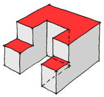
Example of roofs based on rectangle are types: 0.*, 1.*, 2.*, 3.*, 4.*, 5.* ?, 7.*
Examples
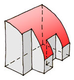
| Type 2.1 | Type 5.2 | Type 5.6 |
|---|---|---|
|
|
 3D view: 3D view: 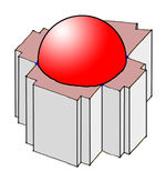
|
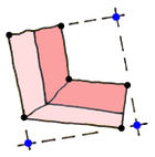
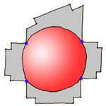
In case of type 5.6 we find the biggest circle inside building polygon. The circle is base for roof sphere (red surface on image, shared points are marked blue) rest of roof is generated flat (gray color).
Generation of building bounding box.
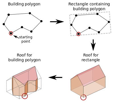
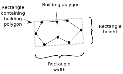
To generate 3D model for building polygon which is not rectangle at first place we need to find the smallest rectangle containing building polygon. It is easy to generate shape of building roof for rectangle and it is easy to place dormers using this rectangle.
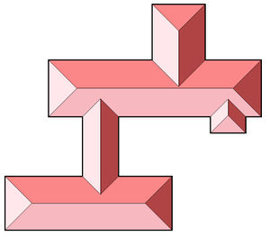
Example of generating roof for complex building polygon:
Roof properties
Because roofs are base on rectangle, rectangle sizes are taken in to account in process of roof generation. Each roof type has properties describing it's shape eg. 3dr:length. If properties are write in presents true size of properties are calculated using presents and rectangle sizes.
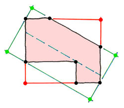
Some times automatically generated bounding rectangle (red color) is not as we expected (green color):
Starting point
When we need to describe roof with precision it is necessary to determinate roof direction. Now day proposals using tag building:roof:orientation= along|across. Unfortunately this tag is not enough because:
1. There are building polygons which are square. In that case value of tag is pointless and there are four way to generate roof model
2. There are roof shapes which have four like type 1.0 or more ways to generate roof model:
next tags leike along, rotated or mirrored make the tagging system prone to errors.
3. Dormers needs to precisely mark where roof “begins”
To precisely mark where roof “begins” we need to choose some point as start point. There is not need to add additional tags for node because building polygon has defined nodes direction. We can use start point as point first point on building polygon.
Warning. Starting point for building polygon is not visible in osm editors!
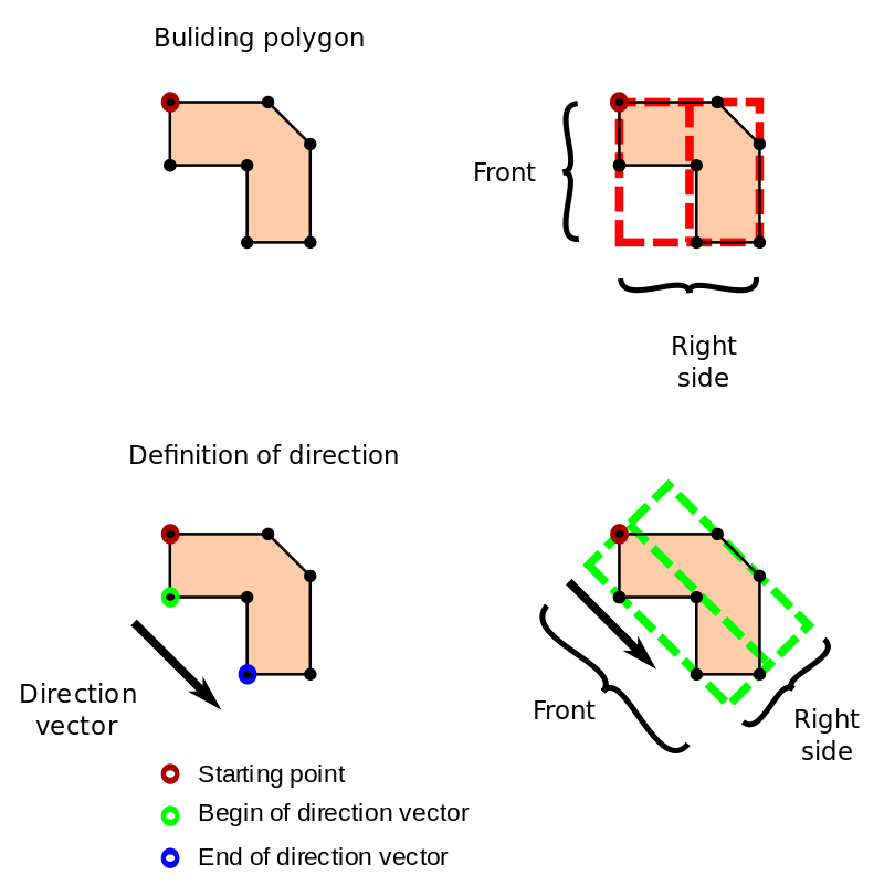
Polygon direction
By default bounding rectangle is generated as the smallest rectangle write on building polygon. Not always we expected this behavior. To change this we need add additional tags describing direction of bounding rectangle. Direction of rectangle affects on location of dormers because it describing where it is front of building.
Example:
Method 1
Using tags assigned to nodes of building polygon. Two of nodes have assigned tag 3dr:direction=begin|end. Method may by used for single buildings which don't share walls.
| Tag | Description |
|---|---|
| 3dr:direction=begin | Begin of vector describing direction of roof. |
| 3dr:direction=end | End of vector describing direction of roof. |
Status Implemented
Method 2
Points describing direction are write using relation. This allow for buildings with shared walls.
Relation type: 3dr
Any node with role 3dr:direction:begin
Any node with role 3dr:direction:end
Warning It may change
Warning Not implemented
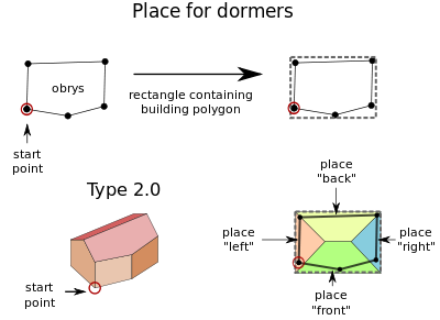
Places for dormers
For roofs base on rectangle there are four place where we can put dormers. Places are connected with edges of rectangle containing building polygon. Example image:
| Places number on roof | Tag | Tag (Alternative) (not working) | Description |
|---|---|---|---|
| place 1 | 3dr:dormers:front | 3dr:dormers:1 | Front |
| place 2 | 3dr:dormers:right | 3dr:dormers:2 | Right side |
| place 3 | 3dr:dormers:back | 3dr:dormers:3 | Back |
| place 4 | 3dr:dormers:left | 3dr:dormers:4 | Left side |
Not for all roofs shapes all four places are available. In example above for roof shape type 2.0 there are only two places for dormers. There are places 1 and 3 (front and back). All others places are ignored.
Warning Currently not implemented. Currently dormers can be setup using tag 3dr:type=2.0.aa.b
Complex roof geometry
The complicated roofs should be described as a sum of single simple components
Name translation
The both descriptions for the roof geometry are compatible. You can write "0.0" or "flat".We are working on understandable description for every roof types.
Names for roof types:[8] :
| "roof table" | "building attributes" |
|---|---|
| 0.0 | flat |
| 1.0 | skillion |
| 2.0 | gabled |
| 2.3 | half-hipped |
| 2.4 | hipped |
| 2.5 | pyramidal |
| 3.0 | half_saltbox* |
| 3.1 | saltbox* |
| 3.2 | corner_saltbox |
| 3.3 | triple_saltbox |
| 3.4 | quadruple_saltbox |
| 4.0 | gambrel |
| 4.1 , 4.2 | mansard |
| 4.3 | helm |
| 5.0 | round |
| 5.2 | half_round |
| 5.6 | dome |
| 6.0 | three_aisled |
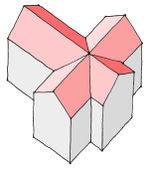
| 6.2 | crosspitched |
| 6.3 | five_aisled |
| 7.1.n | sawtooth |
| 7.2.n | trapeze |
| 7.3.n | gabled_row |
| 7.4.n | round_row |
| 7.5.n | wave |
| 8.0 | cone |
| 8.1 | hyperbolic_paraboloid |
| 8.2 | parabolic |
| 8.3 | hyperbolic_tower |
| 8.4 | elliptic_hyperboloid |
| 8.5 | ellipsoid_cutted |
| 8.6 | elliptic_paraboloid |
| 8.7 | tent |
| 8.8 | geodesic_dome |
| 8.9 | spherical_cutted |
| 9.0 | equal_hipped |
- Note: the common german name for the both roof subtypes is "Berliner Dach". See: [9]
Comparison table with: Image - roof_table - building attributes at: Dachformen.pdf --Geri-oc 18:41, 7 December 2011 (UTC)
