User:Nathhad/Operating Sites and Interlockings
| This page is a draft for a new sub-page for the page OpenRailwayMap/Tagging in North America. The OpenRailwayMap/Tagging page's sections on Interlockings and Operating Sites don't translate well to American practice, and need some guidance (and a reviewed group consensus within the US with respect to the contents of this page) to translate to useful US practice. |
The Operating Site and Interlocking sections of OpenRailwayMap/Tagging do not translate directly to North American practice. The recommendations of this page represent an effort to adapt the default OpenRailwayMap tagging scheme to the North American rail system in a manner that is both self-consistent, and is consistent with the work being done on the European network. One related goal is that if we have adapted the tagging scheme appropriately, all of our sites should also render correctly on the default OpenRailwayMap rendering.
Once the initial labeling of track and routes has been completed, many of the most significant operating features of North American railroads fall under one of three sometimes broad categories:
- Yards: This term is used much more broadly in the Americas than where this tagging scheme was originally developed. Here, a yard is essentially everything that isn't either a main track (which is traffic controlled) or an industry spur. If a yard is mapped in greater detail, its key parts are often collected within an operating site relation.
- Control Points: These are points along a main track where the dispatcher has manual control over the traffic. They are most often one of three different operating site types in the tagging scheme:
railway=junction,railway=spur_junction, orrailway=crossover. Control points which don't fit under one of these tags may be tagged underrailway=site. The parts of a control point will usually be collected within an operating site relation, which may also include an interlocking relation. - Stations: These are points where passengers can access and board trains. They should be tagged
railway=stationfor scheduled stop points (where the train always stops), orrailway=haltfor flag stops (where the train only stops when ticket reservations have been made, and there are passengers to pick up and drop off).
There are two steps to mapping these features. First and most importantly, an operating site node is placed near the center of the site to mark its location. This node serves two purposes: it is the mark for locating the tag in the rendered map, and it serves as a routing point for the site. Second, as the site is mapped in detail, the operating site node and all of the associated parts are collected together into relations.
The following sections all go into detail on how to recognize and tag these various features, including how to tag their most important components and assemble them into the appropriate relations. Illustrations are laid out using the following legend:

Operating Sites vs. Interlockings
The OpenRailwayMap/Tagging page makes the point at least twice that "interlockings are not operating sites," but doesn't go any further in explaining the difference in both concept and tagging. To be more clear, it happens very frequently in North America that interlockings and operating sites coincide. However, they do not have a 1:1 relation with each other, and in fact it is completely possible to have one without the other (though it's fairly uncommon to have an interlocking that isn't at least part of an operating site).
The two often look the same at simple operating sites like crossovers in CTC territory. At these sites, there is both a control point (a place where traffic is directed by the dispatcher, in this case the crossover, which is an operating site), and an interlocking (the remote-controlled signal and switch system the dispatcher uses to exercise that control, which also prevents him from routing one train into a track already occupied by another - that set of safety interlock features is the fundamental part of an "interlocking" from which it gets its name). Those two things both happen to occupy essentially the same space, and one (the interlocking) is part of the other (the control point, which in this case is an operating site that includes its operating site node, the stop positions approaching the entry signals, and the interlocking with all its parts).
However, it is still very, very common, especially on smaller railroads, to have control points that do not include interlockings. For example, this will almost always be the case on lines that still operate under train order control. If two trains are scheduled or ordered to meet at a siding, the train required to take the siding must stop at the first control point (the siding entrance), manually unlock and throw the switch to the siding, pull in clear to the siding to wait at the second control point (the exit), and restore the switch. The second train is then free to pass. This system still uses the same number of control points, but there are no interlockings; the turnouts are manually controlled on the ground, and there are no signals or safety devices to automatically prevent a collision. The operating site relation would include the operating site node, turnout, and stop positions only.
As a counterexample, an interlocking that doesn't coincide with the footprint of an operating site would be an interlocking at the entrance to a passenger terminal. The interlocking itself is only the set of turnouts and signals at the entrance; it is part of the station operating site, but the overall station operating site is much larger than just the interlocking at the entrance.
The section for control points, where there are the most opportunites for confusion here, will also attempt to clarify which parts of the operating site are also part of the interlocking, and how to tag and create the necessary relations.
Yards
- Primary goal: Add the operating site node, with the correct tags, and in the appropriate place.
- Secondary goals: Map turnouts, buildings, landuse, and other supporting facilities that are part of the yard, and collect them into an operating site relation.
Operating Site node location
The original directions for placing the operating site node on OpenRailwayMap/Tagging are a bit less than clear, as they recommend placing the node at the geometric center of the site, except for when you shouldn't. As a clearer explanation of where this point should go, we recommend the "center" of the yard be thought of more in terms a railroad might use, considering a railroad is a "linear feature" on a map (arranged along a path, which might or might not be curved), more than it is an area. Functionally, the center is halfway along the length, whatever circuitous route that length may follow, and halfway from the leftmost to the rightmost track. Following that mode of thought will almost always result in locating the operating point node in a location that will function well, both for label rendering and for any future routing purpose.
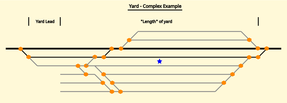
The following illustrations attempt to demonstrate this for both simple and more convoluted yard shapes. The first illustration begins with a simple yard arrangement. The primary feature to be aware of in this first illustration is the yard lead, a common feature which allows crews and their locomotive to work in the yard without needing to encroach on the controlled tracks. While this lead is part of a yard, it is best to ignore when trying to determine the "middle" of the yard for purposes of locating the operating site node.
The next illustration is more complex, and introduces several very common features that the editor is very likely to encounter in smaller real yards.
First, there is a siding next to the main track. Unlike yard tracks, a siding is a controlled track; it is used to allow trains on the main line to meet or pass each other, and operating on it requires the permission of the dispatcher. Sometimes they can be visually distinguished from yard tracks even in satellite photos, but often identifying a siding through a yard will require local knowledge such as in-person observation, or access to documents such as employee timetables or track charts. If an employee timetable is available, they will always identify controlled sidings, as well as distinguish them from short lengths of double mainline.
Second, this yard is divided into three sections that are most likely used for different purposes. The lead is still easy to identify. However, one section is across the main tracks, so will required permission from the dispatcher any time it is to be accessed. However, these are all parts of the same yard.
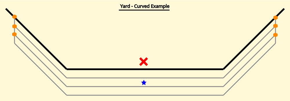
The following example illustrates how these principles apply to a very simple yard on a curve. Simply placing the node at the true geometric center of the yard would probably result in a node around the "X". This is clearly not useful - for many yards, this will result in a node that isn't even within the yard itself, which is less than ideal for both labeling the yard on the map, and for any futrue routing use. Sticking with the above principle of "halfway along the length, even if the length is curved, and halfway between the left and right" gives the location of the blue star, which is clearly more functional.
Yard Types and Tagging
railway=yard vs railway=service_station with examples
Control Points
Very brief explanation of what control points are.


