Proposal:Transformer extension proposal
| The Feature Page for this approved proposal is located at Tag:power=transformer |
| Transformer extension proposal | |
|---|---|
| Proposal status: | Approved (active) |
| Proposed by: | fanfouer |
| Tagging: | transformer=* |
| Applies to: | |
| Definition: | Propose to add extra details about power transformers devices functionalities and specifications |
| Statistics: |
|
| Draft started: | 2017-02-10 |
| RFC start: | 2017-07-31 |
| Vote start: | 2017-09-07 |
| Vote end: | 2017-09-21 |
Rationale
Power transformers are static devices designed to adapt electricity voltage or intensity in an alternating power network.
The amount of flowing energy through the whole network depends of transformers transfer capabilities.
Gather and know functions and figures about transformers can be a concern for data consumers involved in power grid operation or environmental design.
As advanced technical knowledge, mappers may look for a consistent and well described model to guide them when adding such information to OSM.
Currently, the wiki doesn't describe enough tags to know well how each transformer work. They are considered as black boxes with input and output voltages but reality can be more complex actually.
Finally this proposal will help to improve data quality and completeness inside OSM and allow consumers to get a better information on how power infrastructure actually works.
Here is a list of common definitions useful to have in mind :
- Power Transformer (421-01-01) : A static device, with help of electrical induction between metallic windings, converts a given voltage and current to another voltage and current. The delivery is done at the same frequency.
- Winding (421-03-01) : An assembly of metallic wire turns forming a circuit associated with one of the voltages of a transformer. Note on a polyphase transformer, a winding is the combination of phase windings. Interfaces are use to be called primary, secondary, tertiary and so on, which will be useful to adapt tagging scheme in this proposal. The number of windings, or voltage levels aren't limited in theory.
- Auxiliary transformer (605-02-46) : Transformer exclusively intended to supply the internal circuits of a power substation.
- Bank (151-12-11) : Set of devices connected and acting together.
Proposal
It is proposed to add extra tags or values to get a better description of power transformer devices :
- windings=*
- windings:configuration=*
- voltage:primary=*
- voltage:secondary=*
- voltage:tertiary=*
- devices=*
There is no point to replace or deprecate any reviewed key or value here.
Transformers have been tagged for years in OSM, most of the formal work regarding tags had already been done in the substation refinement proposal. This proposal only complete the existing stuff.
This proposal focus on tags to use if, and only if, data is available. It does not assume all data can be publicly known but provide a consistent model to add it to the map if possible, without any power grid operator help.
Where do I find such data ?
First of all, don't go inside power substations if you're not invited to do so please, it's dangerous and probably illegal.
Public information or aerial imagery will help to see outdoor transforming facilities safely.
On every transforming device found (not building, not fence), add a ![]() and put some tags described below like mandatory power=transformer.
and put some tags described below like mandatory power=transformer.
Use location=* to give information about its position and transformer=* to let us know about its function.
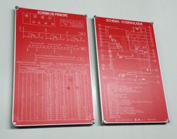
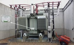
High detailed information may be found on transformers themselves. A complete datasheet as exposed beside gives many figures on the machine capabilities and structure.
We basically need voltages, windings structure but manufacturer=* and start_date=* may also be completed.
Nevertheless, you may not be able to took picture of those plates and as a reminder : don't go inside restricted perimeters to get the one you couldn't. unless invited
Advanced tagging
This chapter gives advanced description of transformers technology and is clearly intended for power specialists/technicians. Following keys aren't mandatory at all and are provided to give a better structure for information eventually obtained during surveys or from license-compatible public documentation.
Sub parts are sorted by level of complexity and knowledge required
It may be good to complete the transformer=* definition with following value :
| Key | Value | Comment |
|---|---|---|
| transformer | auxiliary | Auxiliary transformers intend to supply power to substation internal systems. They're not feeding any subscriber connected to power grid but act as a load on the substation architecture. |
Transformer sets
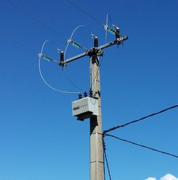
In some situations and countries, polyphase transformers may not be contained in a single box. It's not unusual to find several mono phase transformers boxes assumed as an equivalent to a single polyphase transformer.
This proposal would introduce devices=*, defaults to 1, to indicate how many different boxes you see, sharing the same figures and functions.
It won't be useful to add a transformer: prefix since such a key can be used in many other situations far beyond power field of knowledge.
Such a key will factorise as many features as possible on a same node. Thus, all keys giving figures or functions will have to be valued for a single device.
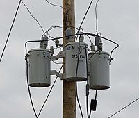
More example are available below, here the principle : 2 similar three-phase 50Hz transformers may be factorised as this on the same node : devices=2 + phases=3 + frequency=50.
Please note that, according to IEC 151-12-11, such disposal of transformers can't be properly called a bank since transformers aren't connected together but each one connected to a different live cable (or even different power circuit). A set would be more appropriate.
An actual bank can't be factorised on the same node (even if at the top of a pole) and for sake of accuracy, you'll have to use as many nodes as devices in the bank. If not, we loose information about the bank structure and how transformers are working together.
Voltage tagging
Transformers are designed to adapt voltage between their windings connected to interfaces. We use to call them primary, secondary and so on.
Each interface is defined with its own voltage and transformers won't have a global voltage value. This proposal aims to discourage the use of voltage=* without suffix on transformers.
It's proposed to use voltage:primary=*, voltage:secondary=* instead according to the interface's name.
| Key | Value | Description |
|---|---|---|
| voltage:primary | Primary interface's voltage | The operating voltage of a given transformer's primary interface. |
| voltage:secondary | Secondary interface's voltage | The operating voltage of a given transformer's secondary interface. |
| voltage:tertiary | Tertiary interface's voltage | The operating voltage of a given transformer's tertiary interface. |
Windings and interfaces description
Transformers are often composed of simple windings facing each other linked to identical primary and secondary interfaces which is pretty nice to tag with a few keys.
And sometimes, you may find 3-phases single primary winding but two 3-phases secondary windings or whatever arrangement you can imagine.
Those complex situations need extended keys to be accurately described in OSM. phases=* and windings=* may be suffixed with :primary, :secondary, :tertiary... to give as specific values as it needs for a specific interface. If no suffix is used, the values will be considered as common to all interfaces of the transformer.
All windings related to an interface (primary, secondary,...) always operate at the same voltage. Different is the voltage, so does the interface.
Let's introduce windings=* also to give the number of windings of the whole transformer. As you will see in examples, and according to IEC 421-03-01, it's a number of windings and not poles.
On a 3-phases interfaces, you'll see 3 poles connected to 3 cables but it counts as 1 winding. Consider taking total amount of cables connected to the transformer divided by phase number to get the actual number of winding.
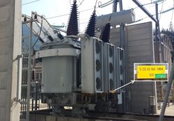
Example: you see 9 cables connected to a 3-phases transformer like beside, 9/3 = 3 for windings=* key.
To describe all interfaces with a single bunch of keys, assuming they all have the same figures/design
| Key | Value | Description |
|---|---|---|
| phases | Phases number | For polyphase systems, like national, regional and local power grids, this key gives the number of phases connected to the transformer. |
| windings | Number of windings for the whole transformer | This key gives the amount of windings for the whole transformer whatever it's for primary, secondary... |
| rating | Global power rating | The power rating going through the transformer, mainly from primary to every other interfaces. |
To describe each interface separately, given with 3 interfaces but keys can be suffixed accordingly if more voltage levels needed :
| Key | Value | Description |
|---|---|---|
| phases:primary | Number of phases composing the primary winding | - |
| phases:secondary | Number of phases composing the secondary winding | - |
| phases:tertiary | Number of phases composing the tertiary winding | - |
| windings:primary | Number of primary windings | Amount of polyphase windings connected to the primary interface of the transformer |
| windings:secondary | Number of secondary windings | Amount of polyphase windings connected to the secondary interface of the transformer |
| windings:tertiary | Number of tertiary windings | Amount of polyphase windings connected to the tertiary interface of the transformer |
| rating:primary | Rating of primary winding | Rating of the primary winding only |
| rating:secondary | Rating of secondary winding | Rating of the secondary winding only |
| rating:tertiary | Rating of tertiary winding | Rating of the tertiary winding only |
Transformer configurations
Since we can know how windings are arranged inside the transformer, it may be good to know how they are connected too. Different connections exists and are called star, zig-zag, open and so on.
This information can't be deduced just by looking at the machine. Engineering documentation have to be publicly available to complete this key.
If you are able to determine how a given transformer windings are connected, you can use windings:configuration=* key as following :
| Key | Value | Comment |
|---|---|---|
| windings:configuration | star | IEC 421-10-01 : All phase windings are all connected to a common point at one side and each one to one pole at the other side as to form an actual star. |
| delta | IEC 421-10-02 : All phase windings are connected to form a closed circuit. Poles are connected between each winding. | |
| open-delta | IEC 421-10-03 : The same as delta configuration except the circuit isn't closed at only one corner. | |
| zigzag | IEC 421-10-04 : | |
| open | IEC 421-10-05 : Each phase winding is independent and not connected to any of its neighbours. | |
| scott | IEC 421-10-06 : Configuration used to change the number of phase between primary and secondary. Used in traction substations fed by 3-phases network (railways use to work in 2-phases mode) | |
| leblanc | IEC 421-10-07 : Same as Scott, configuration used to change the number of phase between primary and secondary. Used in traction substations fed by 3-phases network (railways use to work in 2-phases mode) |
As configurations can be different between several interfaces of a single transformer, previously introduced prefixes fit perfectly with configuration also, as follow :
windings:primary:configuration=*, windings:secondary:configuration=* and so on...
Such a key can also be used on power=converter objects where similar configurations can sometimes be used. Nevertheless, it's out of the scope of this proposal.
Edition management
Values to be replaced
Some pretty used tags should be carefully replaced like suggested below.
It's recommended to check the values of such tags and to not mass edit.
| Obsolete tag | Usage volumetry | Used for ? | New tag(s) to use |
|---|---|---|---|
| voltage=* | ~10 500 on 2017-07-30 | Give a list of used voltages on a |
voltage:primary=* + voltage:secondary=* + ... |
| voltage-high=* | 6 128 on 2017-07-30 | Voltage used on a transformer's primary interface | voltage:primary=* |
| voltage-low=* | 3 996 on 2017-07-30 | Voltage used on a transformer's secondary interface | voltage:secondary=* |
External discussions
- Tagging mailing list about multiple transformers
- Tagging mailing list RFC announcement
- Tagging mailing list RFC discussion
- OSM Forum / DE community
- This proposal talk page.
Examples
Transmission transformers
| Photo | Aerial view | Tagging | Note |
|---|---|---|---|
| -- |
power=transformer
|
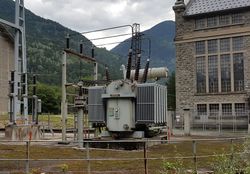
This transformer intends to stup up 6kV power output from a 2 units hydraulic power plant to the 63kV local power grid.
| |
| -- |
power=transformer
|
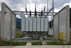
This transformer has 3 windings operating at 3 different voltages. 225kV side is on the foreground while 63kV is hidden at the back
| |
| -- |
power=transformer
|
This plate can be seen on transformer themselves (picture taken with power grid operator acknowledgement) and gives the windings configuration with several other figures. All tags can be defined with it.
|
Distribution transformers
| Photo | Aerial view | Tagging | Note |
|---|---|---|---|
| -- |
power=pole
|
Tranformers can directly be hosted on poles to save ground place and prevent complex infrastructure building when not needed. | |
| -- |
power=pole
|
Multiple mono phase transformers used on a 3-phase network | |
| -- |
power=transformer
|
||
| -- |
power=transformer
|
Such transformer are used in France to feed legacy 15kV distribution zones from current 20kV infrastructures.
|
Traction transformers
| Photo | Aerial view | Tagging | Note |
|---|---|---|---|
| -- |
power=transformer
|
AC Overhead lines of railways are fed from transmission power grid with such biphase transformers. | |
| -- |
On one of each transformer inside of the substation
power=transformer
|
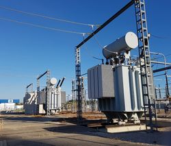
To reduce the voltage drop in AC overhead lines, they can be fed by auto-transformers which take power from a -25kV feeder line going along railways. Typical for these installations is, that there is no connection to the national power grid visible. |
Auxiliary transformers
Voting
- Log in to the wiki if you are not already logged in.
- Scroll down to voting and click 'Edit source'. Copy and paste the appropriate code from this table on its own line at the bottom of the text area:
| To get this output | you type | Description |
|---|---|---|
{{vote|yes}} --~~~~
|
Feel free to also explain why you support proposal. | |
{{vote|no}} reason --~~~~
|
Replace reason with your reason(s) for voting no. | |
{{vote|abstain}} comments --~~~~
|
If you don't want to vote but have comments. Replace comments with your comments. |
~~~~ automatically inserts your name and the current date.For full template documentation see Template:Vote. See also how vote outcome is processed.
20 out of 23 votes. This proposal is accepted
 I approve this proposal. --Waldhans (talk) 00:25, 7 September 2017 (UTC)
 I approve this proposal. --Hufgardm (talk) 06:01, 7 September 2017 (UTC)
 I approve this proposal. --Michalfabik (talk) 06:46, 7 September 2017 (UTC)
 I approve this proposal. --Buchanan (talk) 08:15, 7 September 2017 (UTC)
 I approve this proposal. --Sommerluk (talk) 09:11, 7 September 2017 (UTC)
 I approve this proposal. --Crochet.david (talk) 11:04, 7 September 2017 (UTC)
 I approve this proposal. Fanfouer (talk) 11:12, 7 September 2017 (UTC)
 I approve this proposal. --sorcrosc (talk) 16:00, 10 September 2017 (UTC)
 I approve this proposal. If rating is always in VA, it would be better, IMHO, to not give unit nor multiplier, and only give the full number, that is to say rating=20000000 instead of rating=20 MVA; that would ease data consumption by scripts. Besides, it could be useful to define, in the wiki pages for *:primary=*, *:secondary=* and so on, to define how to tell from a transformer which one is the primary, the secondary or the tertiary, as, AFAIK, it can only be told by analysing the layout of the substation, to deduce the current flow from it. I assume primary is the electricity input, but am not sure, and the proposal does not dissipate this doubt. --Penegal (talk) 08:04, 11 September 2017 (UTC)
 I approve this proposal. --Renecha (talk) 22:19, 12 September 2017 (UTC)
 I approve this proposal. --Agamitsudo (talk) 05:05, 13 September 2017 (UTC)
 I approve this proposal. --Ryra6453 (talk) 05:49, 13 September 2017 (UTC)
 I approve this proposal. --Gnrc69 (talk) 12:26, 13 September 2017 (UTC)
 I approve this proposal. --JeaRRo (talk) 09:11, 14 September 2017 (UTC)
 I approve this proposal. --Al-Hun (talk) 09:32, 15 September 2017 (UTC)
 I approve this proposal. --Gourmet (talk) 02:25, 19 September 2017 (UTC)
 I have comments but abstain from voting on this proposal. voltage-high=* must not be replaced by voltage:primary=*. This is only true when down-transforming. voltage-low the same. --Seichter (talk) 16:05, 19 September 2017 (UTC)
- This is exactly what the proposal recommends: voltage-high=* used for transformer's primary interface (theoretically for down transforming) Fanfouer (talk) 18:09, 19 September 2017 (UTC)
- No, the recommendations in "values to be replaced" are misleading: When up transforming, voltage-high has to be replaced by voltage:secondary, voltage-low by voltage:primary Seichter (talk) 10:36, 20 September 2017 (UTC)
- Ok I agree, there is indeed an issue. Primary can be defined as power plant side and secondary as consumer side which doesn't settle any order in voltages. Then voltage-up and voltage-down can be really carefully replaced depending on which side (power plant or consumer) it regards, can't you ? Guidelines should be updated (maybe in postvote cleanup) to reflect this, i'm ok with this Fanfouer (talk) 12:18, 20 September 2017 (UTC)
- No, the recommendations in "values to be replaced" are misleading: When up transforming, voltage-high has to be replaced by voltage:secondary, voltage-low by voltage:primary Seichter (talk) 10:36, 20 September 2017 (UTC)
 I have comments but abstain from voting on this proposal. Not convinced yet. First, most of the detailed data (such as windings:configuration=*) can hardly be ascertained in a legal way (taking telephoto pics through fences from inside private property might be frowned upon by the proprietor’s solicitors), and I strongly doubt the operators to be much amused to see such detailed data being distributed in a public free database. Second, as for the example of the three transformers on the pole, IMHO they should have a transformer:location=pole to describe them being mounted to the pole. And is it clear enough that the devices=* and other keys do refer to the transformers instead of the pole itself (which is the main tag here)? IMHO transformer:devices=* etc. would be clearer. --Kreuzschnabel (talk) 16:39, 19 September 2017 (UTC)
- If it's illegal, don't use the tag. The proposal clearly stands to don't go inside restricted perimeters. I have public documentation or enough knowledge to deduct this information but it doesn't convert me into illegal things.
- Good point for transformer:location=* or transformer:devices=*. It's not incompatible with what the proposal stands for, it may be good to ask during RFC. I can't change the example, but it can be explained in the new tag page once accepted (if so at the end of vote). Would you consent to change your opinion? Fanfouer (talk) 18:09, 19 September 2017 (UTC)
 I oppose this proposal. --Skinfaxi (09:15, 7 September 2017 (UTC)
 I approve this proposal. Though not much active in mapping power lines, this would be helpful for tanging transformers (especially those on poles), though the new tags looks technical in background. -TagaSanPedroAko (talk) 15:20, 20 September 2017 (UTC)
 I approve this proposal. --Marc CH (talk) 20:28, 20 September 2017 (UTC)
 I approve this proposal. After thinking about the proposal and discussing it in the German forum I agree with your proposal. There are sometimes good reasons to change tags although it should be avoided (own experience as a designer of railway tags). Adding examples of the German 16.7 Hz system would be a plus if you add examples of the French AC railway power system. --Nakaner (talk) 22:10, 20 September 2017 (UTC)
 I approve this proposal. To me the proposal seems to have a good structure.
- I am only irritated by the first example in the section "Traction Transformers": is that really 2phase, not 1-phase plus neutral line? In the picture there are 3 congeneric transformers in parallel. As Nakaner wrote, an example from a single phase traction system like in Norway, Sweden, Germany, Austria, Switzerland would be nice. --Rainero
- Thanks to you both for your votes and comments.
- Examples will be completed on postvote phase to add more cases, like 16.7 Hz systems which are more widely used than the two-phases French one.
- Traction transformers in examples are indeed 2-phases+neutral like in this chart Fanfouer (talk) 10:11, 21 September 2017 (UTC)
- Merci pour élucider ça pour moi --Rainero 21:59, 21 September 2017
Post-vote cleanup
Here are resources related to post-vote cleanup of this proposal.
- power=transformer
- windings=*
- JOSM updating preset ticket #15367
- iD preset updating #4442

