ProposedRoofLines
Roof lines can be traced in order to improve rendering of buildings. This could be used in 3D applications and isometric maps. Please note that this example is just a mockup and does not exist in the OSM database in this form. But the building footprint has been exported from OSM [1].
Motivation
Reconstructing roof shapes from meta information and attributes can become extremely difficult. Roof type and orientation could be easily tagged but require an algorithm for guessing the position and alignment of roof ridges, edges and angles. It could work for very simple rectangular building shapes. But not for complex footprints imported from cadastre data. As an alternative, roof lines could be traced directly from imagery
Approach
Roof lines are traced as ways and nodes and connected to the building via relations. There are two types of roof lines:
1. Ridges tagged as roof:ridge=yes. Ridges are strictly horizontal and the height is fixed by an additional attribute
2. Edges connecting the ridges with the eaves tagged as roof:edge=yes. Although they could be guessed it is better to include them in order to create closed rings for easier processing.
Tips could be defined as nodes tagged as roof:apex=yes. They are connected to the rest using roof:edge as well.
-
 Roof ridges highlighted in red
 -
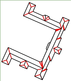 Roof edges highlighted in red
 -
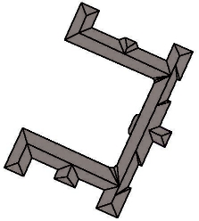 Rendering in 2D
 -
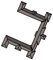 Shaded rendering in 2D


The areas between eaves, edges and ridges are expected to be coplanar so that they can be easily polygonized. Some buildings have little jutties and ledges along the edge. In this case the intersection of the roof surface with the wall must be approximated so that the roof surface remains flat. Im my example the ledge in the middle of the building would be modeled by adding a flat top. Alternatively, the roof surface could continue downwards cutting away a part of the wall.

Measuring heights
There are mainly two tags available for estimating building heights, height=* and building:levels=*.
They measure the distance from ground to the roof top/ridge. What is missing is the height of the roof base. It can be either explicitly set by building:eaves:height=* or building:eaves:levels=*, or it can be calculated if other attributes are available, e.g. roof:height=* and roof:angle=*.
Deriving the roof base height from the ridge and the inclination of the roof surface (roof:angle=*) is possible, however this requires a very exact tracing of ridges and is error prone.
The Following combinations are possible:
building:levels=6, building:eaves:levels=4. Assuming that one level is 3m high, we get height of ridges = 18m, height of roof base = 12m.
building:levels=6, building:eaves:height=12. Mixture of metric value and levels. Also possible.
building:levels=6, roof:angle=30. Height of roof base depends on distance between ridge and eaves edges.
building:levels=6, roof:height=6. eaves:height = 6*3m - 6m = 12m.
height=18, building:eaves:levels=4. Mixture of metric value and levels. Also possible.
height=18, building:eaves:height=12. Exact measurements.
height=18, roof:angle=30. Height of eaves depends on distance between ridge and eaves edge.
height=18, roof:height=6. eaves:height = 18m - 6m = 12m.
building:eaves:levels=4, roof:height=6. height = 4*3m + 6m.
building:eaves:levels=4, roof:angle=30. height depends on distance between ridge and eaves edge.
building:eaves:height=12, roof:height=6. height = 12m + 6m.
building:eaves:height=12, roof:angle=30. height depends on distance between ridge and eaves edge.
Note that the result may be undefined if too many and conflicting attributes are present.
Using one the above tagging scheme and adding a few lines could work for the majority of small residential buildings. For more complex buildings with many ridges it is necessary to attach the exact height to the ways directly: roof:ridge=yes and building:ridge:height=*. If this attribute is present, it supersedes the attributes attached to the building. In the example on this page you can see one part on the right which is a bit lower than the main roof. Its ridge is tagged with a height value.
Building Relation
Roof structures must be connected to buildings using relations. Otherwise it would be difficult to detect, which ways tagged as roof lines belong to which building. The following table is based on the Relations/Proposed/Buildings proposal and on Multipolygon, which is often used for complex buildings.
Tags
| Key | Value | Discussion |
|---|---|---|
| type | building | A relation that combines all node, ways, and other relations that belong to a single building. |
Members
| Way, Node, Area or Relation | Role | Recurrence? | Discussion |
|---|---|---|---|
| outline | zero or more | The building footprint that is used for 2D renderings. If building parts are present, the outline member shall not be used for building the 3D model. | |
| label | zero or one | This should be used to set the name of the building and to tag the whole building as a POI if desired. The idea behind this is, that this mark should tell the renderer where the name and maybe the symbol of the building should be displayed. That could be necessary if the building includes many details.
This single node could be used also to mark a building if the walls can not be drawn. | |
| entrance | zero or more | Entrances into the building. Big entrances could be areas, but mostly a single node is enough. They might have to be individually tagged as to what kind of entrance they are. There are existing some proposals for entrances (examples:Proposed features/entrance, Tag:railway=subway entrance), so tag it as you like.
Also entrances can be used to tag different adresses of a building. See section "Postal Address Information" above. | |
| contains | zero or more | This should be used for POIs inside a building. If you have detailed information of such POI (separate entrance, different address or something like that), you should better build a separate building relation for each POI and than put this relations as members in right here. | |
| address | zero or more | This should be used for nodes and relations, who were only tagged with address informations. See section "Postal Address Information" above. | |
| part | one or more | Building parts. These parts differ from each other in terms of height, roof-shape, colour, material, ... The part members may be closed ways tagged as building:part=yes or multipolygon relations. | |
| ridge | zero or more | Ways which make up the roof ridges of a building or building part. | |
| edge | zero or more | Ways which make up the roof edges of a building or building part. |
Use and Limitations
This form of roof tracing could be accomplished with current OSM editors. Some nodes may overlap with existing ways like the tip node of a gable. A very small displacement could help. In general, vertical structures and overhanging structures cannot be captured with this approach. For example, overhanging roof parts at the eaves are not possible, but this is a very small detail. Also, modeling post modern skyscapers like this one [2] could be difficult and 2D views in editors could become cluttered. But this one [3] could be possible.
Tutorial on how to model roofs in JOSM
This sections is intended to provide some guidelines on how complex roof structures can be modeled using the popular JOSM editor. Although JOSM is designed as a 2D editor, it can be used to add roof details to building footprints, but it requires a good sense of spatial imagination. JOSM provides some tools such as arranging rings to form rectangular shapes and straighten lines, which are quite useful for our task. It also allows to switch between different image sources and detects whether high quality local imagery is available, making it easy to pick the besst possible source for tracing roof lines. In the following example I use the same building as above and focus on the lower left part. The structure of this building is quite complex. It featurese a hipped roof, many dormers, ledges, some portals with figures on them, varying roof heights, round staircases etc. Most problematic is that the height of the roof base or eaves is not consistent and that the roof stretches down to lower levels at the wings. A possible solution to fix this is to split the building into several parts so that the building:eaves:height tag could be assign accordingly. However, in this example, I use vertical roof structures to model facade parts that reach higher than the specified eaves height, so that the 2D rendering remains unaffected.
Step 1: trace horizonal lines

First, trace the horizonal lines along the eaves and ridges. The outer eaves line is tagged as building and should already contain information on maximum roof height, roof type, architecture, facade and roof colors, etc. The topmost roof:ridge=yes line must contain a height value, measured from the bottom of the building (ground level). Insert an additional roof:ridge=yes line at the sharp kink between the lower and the upper part of the roof. Provide exact height values for all ridge lines (default unit is meters). Use the according JOSM tool to make these line rectangular, so that all angles are either 90 or 180 degrees.
Step 2: correct perspective distortions

All lines traced from aerial imagery are positioned incorrectly, due to the perspective distortions. At large buildings you might even see that vertical edges have different angles. This is because aerial imagery is never exactly oblique, even if it has been rectified. For the sake of simplicity, we assume that at least the proportions of structures at the same height level are already correct. In our example, we assume that the roof is axis symmetric along the outer lines. Select all lines with the same height value and move them so that all distances betweem them and to the outer ring are equlized (a'=d', b'=c', e'=h', f'=g').

Step 3: add vertical parts

The small side wing on the right side of the image has an additional full floor and the facade is higher. Thus the roof also starts at a higher level. The gap between the regular eaves and the bottom of the roof must be filled with a vertical roof part. Draw an additional line with 3 edges near the outer ring. This line represents the upper part of the vertical face. Assign the tag roof:ridge=yes to this line and add the correct height value. Then connect this line with nodes of the outer ring. Add tag roof:edge=yes to these connecting lines. Finally move each node so that the line lies exactly over the building eaves. Zoom in to get better precision.
Step 4: add connecting roof lines

Now that we have all the horizontal lines, we must connect them in order to form polygons that can be rendered by 3D software. Add connecting edges between the ridge lines and the outer rings by connecting the nodes. Tag these lines as roof:edge=yes. Straighten lines using appropriate JOSM tools if necessary. Please note that the polygons that are formed in this way must be coplanar. For 3D rendering, the polygons must be triangulated, and if their vertices do not lie exactly on a plane, then this will be visible due to the slightly different surface angles between triangles. In order to avaoid such effects, try to avoid polygons with more than 4 nodes. Also try to make ridge lines parallel to each other.
Step 5: add portal

There is a portal with a plat top at the left side of the building. First draw a ring represting the top edges and tag it as roof:ridge=yes and add the correct height value. You don't need to take care about the exact shape yet. Only the topology is important while drawing. Add the bottom edge as roof:ridge=yes and use the building eaves height as height value. Fill the vertical lateral parts by adding roof:edge=yes lines. Finally move the modes so that the top becomes rectangle and the left side is aligned with the outer ring of the building.
Step 6: move roof to final position

Now that we have finished the roof, we must move it to the final position. So far we modeled at the roof base height, but the final building footprint must be at the location where the building touches the ground. Select everything and move it where it belongs.
Pitfalls

Correctly placing dormers can be problematic because the position where the dormer touches the roof surface cannot be seen in a horizontal projection of a 3D model. It is advisable to know the height of the dormer and to tag it explicitly, instead of relying on some functions to derive it from the roof shape. Although the curve or line at the upper part between the dormer and the roof can be traced from the imagery, it is difficult to capture the the exact position on the 3D plane that defines the roof facet on which we want to place the dormer. Either the dormer penetrates the roof or a gap occurs. While the first case is unproblematic for 3D rendering, gaps should be avoided. However, they can only be detected in the final 3D rendering, because there is no tool for placing points on an inclined surface as of yet. In order to fix gaps, move the nodes at the upper part slightly inwards.
Links
- OSM2World is the only renderer that supports these tags[1]
- 3D_Development
- 3D_Development/Modelling
- 3D_Development/Tagging
- Simple_3D_Buildings
- Roof_modelling
- Relations/Proposed/Buildings
- Buildings
- Indoor
- OSM-3D
- Glosm
References
- ↑ Based on taginfo. See also this post for a rendering example of
roof:ridge=yes.